


This week we focus on minimising thermal bridging at the junctions between the roof and the walls
Before I come on to how we plan to construct the roof at Denby Dale I wanted to share with you some research that has been done on the house. We all appreciate that the Code for Sustainable Homes has been highly laudable in pushing the sustainability agenda in the construction industry. However, we share the growing concerns about the methodology it uses to assess energy consumption and the way it does not adequately prioritise the performance of the building envelope.
We have recently gone public with a study undertaken by a CSH assessor and consultant Jim Parker from 1st Base Projects. Jim looked at the Denby Dale Passivhaus in the context of CSH and found that it would only meet CSH level 3 criteria for Ene 1: Dwelling Emission Rate, the mandatory aspect of the Code’s Energy category. This is despite the fact that the Denby Dale Passivhaus is being built with a tried and tested European Passivhaus methodology and is projected to be one of the most energy-efficient buildings in the UK (with lower space heating demand and better airtightness than, for example, the Code 6 Kingspan Lighthouse at the BRE Innovation park). If by 2016 all houses will need to be built to CSH 5 plus, then the Denby Dale Passivhaus, one of the most efficient houses in the UK, would, in effect, be illegal.
CSH relies on the Standard Assessment Procedure (SAP) for calculating energy needs. SAP has been around since the 1970s and, in our opinion, cannot adequately assess buildings built to this level of performance. Jim Parker’s report highlights many reasons why SAP 2005 fails to accurately estimate the carbon dioxide emissions of low energy housing and echoes some of the Association of Environment Conscious Builders’ (AECB) recent findings when it compared SAP with Passivhaus PlanningPackage (PHPP) – the tool for showing compliance with Passivhaus standards. Maybe the revised SAP will offer some improvements and we would be interested to see how the Denby Dale Passivhaus would perform in SAP 2009. Personally, I think the Code should get rid of SAP and incorporate the more accurate PHPP as its energy calculation methodology. It will be interesting to see how the Code develops over the next few years.
On site
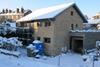
The final scaffolding lift is complete, and we’ve got the timber wall plates in position. One of the gable ends is built up but we’ve left the other gable to allow access to manually pull the roof trusses across the width of the house. We’re not hiring a crane as the trusses aren’t heavy enough to warrant that, but we will need plenty of labour on site. The sooner we get the roofing membrane on the better, then we’ll be protected from the elements just in time for the autumn. We’re expecting the roof trusses to be delivered within the next couple of days.
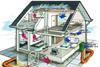
We now need to address the junction between the roof and the walls, taking into account the first floor ceiling. As I’ve said previously, when building a Passivhaus or low energy building the junctions are where it all happens and where care is especially needed. This week, I will be looking at how we maximise super-insulation and minimise thermal bridging at the junctions between the roof and walls.
In a typical UK build, roof trusses are detailed in such a way that the insulation between roof and walls is not continuous and subsequently there is usually a very bad cold bridge, not to mention ensuing airtightness problems at the junction. Such detailing effectively destroys all the good work put into having low U values in wall and roof.
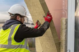
We are using a fairly standard timber truss system - but what is not standard is that it will have 500mm upright elements (‘Bob Tail’ trusses) which will allow the insulation to be fully continuous. The upstand of the truss allows us to bring the 500mm mineral wool quilt insulation in the roof space right through to meet the 300mm Dri-Therm insulation within the cavity wall, ensuring that we won’t have a cold bridge or lose heat at this point.
Thermal bridging will always occur in buildings but our job is to minimise it. The main thermal bridge at this juncture will occur through the ceiling and up the supporting members within the timber trusses to the outside. We will aim to minimise this by the use of slim members (dimensions 100mm x 38mm) and use of timber, as opposed to metal. The ‘journey’ that the heat would have to travel would also be fairly tortuous. All thermal bridges have been thermally modelled in Therm and included within the PHPP building assessment. It is worth pointing out that normal SAP calculations would not have picked up on any of these thermal bridging issues.

1. 'Bobtail' timber roof trusses
2. 500mm fibreglass quilt
3. 300mm fibreglass wall batts
4. 18mm OSB airtightness layer and support for insulation
5. Service void
6. Noggins for wind tightness
7. 900mm overhang for summer shading
Postscript
Bill Butcher is director at Green Building Store


4 Readers' comments