


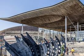


This CPD focuses on technical rules which apply in the EU for the design of timber structures. It is sponsored by Metsä Wood

How to take this module
UBM’s CPD distance-learning programme is open to anyone seeking to develop their knowledge and skills. Each module also offers members of professional institutions an opportunity to earn between 30 and 90 minutes of credits towards their annual CPD requirement.
This article is accredited by the CPD Certification Service. To earn CPD credits, read the article and then click the link below to complete your details and answer the questions. You will receive your results instantly, and if all the questions are correctly answered, you will be able to download your CPD certificate straight away.
CPD CREDITS: 60 MINUTES
DEADLINE: 1 APRIL 2016


INTRODUCTION TO EUROCODES
Eurocodes are a set of harmonised technical rules developed by the European Committee for Standardisation for the structural design of construction works in the EU. They govern the design and calculation process of buildings and all other types of structures, and incorporate geotechnical aspects, structural fire design, situations such as earthquakes, temporary structures and so on.
The purposes of the Eurocodes are:
- To prove compliance with the requirements for mechanical strength and stability and safety in case of fire established by EU law
- To provide a basis for construction and engineering contract specifications
- To provide a framework for creating harmonised technical specifications – the CE marking scheme – for building products.
In total, there are 10 Eurocodes. These are as follows:
- EN 1990 (Eurocode 0): Basis of structural design
- EN 1991 (Eurocode 1): Actions on structures
- EN 1992 (Eurocode 2): Design of concrete structures
- EN 1993 (Eurocode 3): Design of steel structures
- EN 1994 (Eurocode 4): Design of composite steel and concrete structures
- EN 1995 (Eurocode 5): Design of timber structures
- EN 1996 (Eurocode 6): Design of masonry structures
- EN 1997 (Eurocode 7): Geotechnical design
- EN 1998 (Eurocode 8): Design of structures for earthquake resistance
- EN 1999 (Eurocode 9): Design of aluminium structures
Each member state defines National Annexes to each standard to take into account local differences concerning geography, climate and traditional building practices. The safety level remains the responsibility of the government of each member state and differs from state to state. In the UK, the Eurocodes are incorporated into British Standards – so, for example, Eurocode 0 is referred to as BS EN 1990.
With the exception of EN 1990, each of the Eurocodes is divided into a number of parts covering specific aspects. All of the codes relating to materials have a Part 1-1, which covers the design of buildings and other civil engineering structures, and a Part 1-2 for fire design. The codes for concrete, steel, composite steel and concrete, timber structures and earthquake resistance have a Part 2 covering design of bridges. These should be used in combination with the relevant Part 1.
In total, the 10 Eurocodes contain 58 parts.
BS EN 1990: BASIS OF STRUCTURAL DESIGN
BS EN 1990, or Eurocode 0, is the central document in the Eurocodes suite, and provides the framework within which design must be carried out. It is the first operational “material-independent” design code, providing the basic principles of structural design in the main construction materials – concrete, steel, masonry, timber and aluminium – as well as covering a range of disciplines, including fire, geotechnical, seismic and bridge design.
At the heart of BS EN 1990 is the concept of “limit state design”. Limit states are the acceptable limits for the safety and serviceability requirements of the structure, beyond which failure occurs. Structural and load models are set up for each limit state and the design is verified by demonstrating that none of the states will be exceeded when design values are added to the model representing various actions, material or product properties, or geometries.
There are two classifications of limit state: ultimate limit states (ULSs) and serviceability limit states (SLSs). ULSs address the potential for collapse, the safety of people and of the structure under the maximum design load. The following ULSs need to be verified:
- Loss of static equilibrium of the structure or a structural element
- Failure or excessive deformation of a structure or structural element
- Failure or excessive deformation of the ground where the strengths of soil or rock are significant in providing resistance
- Fatigue failure of the structure or structural elements.
SLSs, meanwhile, deal with the functioning and appearance of the structure as well as the comfort of users. These limits always have to be agreed with the customer. SLSs cover:
- Deformations that affect appearance, that cause damage to finishes or non-structural members, that affect user comfort and the functioning of the structure
- Vibrations that cause discomfort to users or limit the functionality of the structure
- Damage that adversely affects appearance, durability or the functionality of the structure.
Under BS EN 1990, the limit states are related to design situations that the structure might experience during its life. These are classified as persistent, transient, accidental or seismic.
- Persistent design situations refer to conditions of normal use. In the case of a highway bridge, for example, this will include the passage of heavy vehicles since the ability to carry heavy vehicles is a key functional requirement
- Transient design situations refer to circumstances where the structure is itself in some temporary configuration, such as during execution or repair
- Accidental design situations refer to exceptional circumstances where a structure is experiencing an extreme event
- Seismic design situations are when the structure is subjected to an earthquake.
BS EN 1990 also classifies variables such as the types of action imposed on the structure. Actions are divided into three classes:
- Permanent. These are actions that remain monotonic and will vary by a negligible amount over time – for example, self-weight, fixed equipment, fixed partitions, finishes and indirect actions caused by shrinkage and/or settlement
- Variable. These are the actions that do not remain monotonic and may vary with time – for example, imposed loading, wind, snow and thermal loading.
- Accidental. For example, an explosion or impact loading.
Variable actions can either be represented by a “characteristic value” or three other design values that incorporate a reduction factor:
- The “combination value” takes into account the reduced probability of simultaneous occurrence of the most unfavourable values of several independent variable actions
- The “frequent value” is a time-related function and sets an upper limit for the value of the variable action to which it applies
- The “quasi-permanent value” is also a time-related function and converts variable actions to equivalent permanent actions in order to derive the creep loading on the structure.

BS EN 1991 ACTIONS ON STRUCTURES PART 1-1
Like BS EN 1990, BS EN 1991 (or Eurocode 1) is relevant to all structural materials, and gives characteristic values for densities, self-weight and imposed loads for different types of building. For imposed loads, buildings are divided into four categories:
- A: Areas for domestic and residential activities – such as rooms in residential buildings and houses, bedrooms and wards in hospitals, and bedrooms in hotels
- B: Office areas
- C: Areas where people may congregate (with the exception of areas defined under A, B and D1))
- C1: Areas with tables, etc.
- C2: Areas with fixed seats
- C3: Areas without obstacles for moving people
- C4: Areas with possible physical activities such as dance halls, gymnastic rooms, stages
- C5: Areas susceptible to large crowds such as concert halls, sports halls including stands, and railway platforms
- D: Shopping areas
- D1: Areas in general retail shops
- D2: Areas in department stores
The characteristic imposed loads for these areas are shown in the table below:
| Category | Uniformly distributed load qk (kN/m2) | Point load Qk (kN) |
|---|---|---|
| A: floors | 1.5-2.0 | 2.0-3.0 |
| A: stairs | 2.0-4.0 | 2.0-4.0 |
| A: balconies | 2.5-4.0 | 2.0-3.0 |
| B | 2.0-3.0 | 1.5-4.5 |
| C1 | 2.0-3.0 | 3.0-4.0 |
| C2 | 3.0-4.0 | 2.5-7.0 |
| C3 | 3.0-5.0 | 4.0-7.0 |
| C4 | 4.5-5.0 | 3.5-7.0 |
| C5 | 5.0-7.5 | 3.5-4.5 |
| D1 | 4.0-5.0 | 3.5-7.0 |
| D2 | 4.0-5.0 | 3.5-7.0 |
Provided that a floor allows a lateral distribution of loads, the self-weight of movable partitions may be taken into account by a uniformly distributed load, which should be added to the imposed loads of floors obtained from the table above.
Snow loads
Snow loads are a variable action and should be assumed to act vertically. They are calculated by first taking the characteristic value of the snow load on the ground. This is usually determined from records of snow load or snow depth measured in well-sheltered areas. The characteristic value is defined as having an annual probability of being exceeded of 0.02.
To determine the snow load on the roof, this characteristic value is multiplied by a snow load shape coefficient, which takes into account whether or not the snow has drifted, the roof shape and climatic conditions. The load is further adjusted using exposure and thermal coefficient factors to address site topography and the amount of heat lost through the roof.
Wind loads
Wind action is represented by a simplified set of forces whose effects are equivalent to the extreme effects of turbulent wind. The fundamental value of basic wind velocity is defined as the 10-minute mean wind velocity with a 0.02 annual risk of being exceeded, irrespective of direction and season, at 10m above ground level in Category II terrain, which is open country with low vegetation and isolated obstacles with separations of at least 20 obstacle heights. While the 10-minute averaging period is the meteorological standard for much of continental Europe, some individual countries use 1 hour, including the UK and Germany. Both these countries have adopted a factor of 1.06 to adjust the measured 1-hour average data to the 10-minute period.
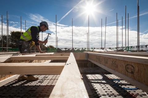
BS EN 1995: TIMBER
In 2010, British Standards Institution withdrew BS 5268 and replaced it with BS EN 1995 (Eurocode 5). The new standard enables the design of a greater range of timber products and solutions and is more flexible than BS 5268.
Ultimate limit state
As outlined above, the structural models in the Eurocodes use characteristic values, which are then reduced by factors. This is especially important in timber design, as BS EN 1995 requires structural engineers to use a modification factor that takes into account the effects of duration of load, moisture content, temperature and any other relevant parameters. A second factor takes into account the possibility of the characteristic value of a material property (for example, strength or stiffness) being less than the specified value and also the effect of scatter around the mean value of the conversion factor.
Deformation
In BS EN 1995, a value for the deformation of a structure or structural member is required at two stages:
- When the loading is immediately applied – this is called the instantaneous deformation
- After all time-dependent displacement has taken place – this is called the final deformation.
The Eurocode uses a deformation factor to calculate the final deformation of the structure. This factor is dependent on the type of material being stressed, as well as its moisture content. Values for the factor have been derived for timber and wood-based materials at defined environmental conditions when subjected to constant loading at the SLS over the design life. These factors are given in BS EN 1995, Table 3.2.
BS EN 1995 does not give ultimate values for deformation limits, but the National Annex provides recommendations.
Vibration frequency
BS EN 1995 is also concerned with the vibrational serviceability of residential timber-based floors. It includes a method to verify the SLS of vibration in floors with a fundamental frequency greater than 8Hz. This is based on calculating the deflection under a 1kN load (the footfall effect).
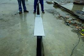
Connections – metal fasteners
Steel-to-timber connections listed in the Eurocode include tooth plates, screws (self-driving, tap, stainless, coated), square and round nails, dowels and bolts. Mechanical connection design is based on values for the embedment strength of the timber material and the yielding moment of the fastener, and follows the theory of timber connections set out by KW Johansen in 1949. The characteristic embedded strength depends on the material and type of connection, and this also determines the spacing between connectors. The spacing is often a key influence on the size of structural members.
The design of fasteners should consider the deformation of the connection and the stiffness of embedded connectors – known as the “slip modulus”. In some instances, a more flexible connection is advisable as it tolerates more movement of the structure. However, if the joints are too flexible this will influence the internal forces analysis.
Connections – glue joints
Glue joints should be designed so that the adhesive is stressed in shear, with few, if any, secondary stresses to cause tension.
Glued connections are mainly produced by a manufacturer in a humidity-controlled environment, and cannot easily be done on site. This can lead to problems with transportation, making the project expensive or even unfeasible. The main principle is that the glue line has to be stronger then the connecting timber. The glues for the connection must comply with BS EN 301, which does not permit on-site gluing.
The typical connection is a finger joint. All types of finger joint connections are categorised as very stiff connections, with a brittle failure mode. Those types of the connections are deemed best for redistributing the bending moment and the slip modulus is minimal.
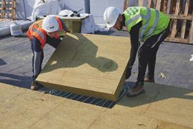
Part 1-2: General — Structural fire design
Fire safety involves prevention, detection, containment and evacuation. The ignition of combustible materials can be prevented by controlling either the source of heat, reducing the combustibility of the materials or providing protective barriers. Careful consideration of design and detailing, insulation and maintenance of the building and its components is essential.
Timber and wood-based materials comprise mainly cellulose and lignin, which are combustible and will burn if exposed to an ignition source under suitable conditions. But this does not mean that timber is an unacceptable material for construction use. Often the opposite is true. When timber burns, a layer of char is created, which helps to protect and maintain the strength and structural integrity of the wood inside. This is why timber in large sections can often be used in unprotected situations where non-combustible materials such as steel would require special fire protection.
There are two methods in BS EN 1995-1-2 for calculating fire influence on a timber element’s resistance. They are the reduced cross-section method and the reduced properties method.
The UK National Annex determines that the cross-sectional properties in fire should be determined using the reduced cross-section method of 4.2.2. In this method, an effective cross-section should be calculated by reducing the initial cross-section by the effective charring depth.
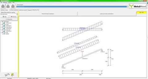
To help designers of timber structures to comply with the relevant Eurocode, Metsä Wood UK has developed Finnwood, a single-member calculation software, available free of charge. Finnwood can be used for the structural calculation of floor joists, roof beams and columns made from Metsä Wood engineered wood products such as Kerto LVL, Finnjoist and Metsä Wood glulam. The software enables designers to freely choose the geometry of the element such as span, support width, slope and loading. After setting initial parameters, it calculates the optimal section size and prints out full structural calculations. It designs according to BS EN 1995-1-1 (Eurocode 5) and its UK National Annex, and has been verified by TRADA Technology. Finnwood can be downloaded from http://www.metsawood.co.uk/finnwood
How to take this module
UBM’s CPD distance-learning programme is open to anyone seeking to develop their knowledge and skills. Each module also offers members of professional institutions an opportunity to earn between 30 and 90 minutes of credits towards their annual CPD requirement.
This article is accredited by the CPD Certification Service. To earn CPD credits, read the article and then click the link below to complete your details and answer the questions. You will receive your results instantly, and if all the questions are correctly answered, you will be able to download your CPD certificate straight away.
CPD CREDITS: 60 MINUTES
DEADLINE: 1 APRIL 2016
Privacy policy
Information you supply to UBM Information Ltd may be used for publication and also to provide you with information about our products or services in the form of direct marketing by email, telephone, fax or post. Information may also be made available to third parties. UBM Information Ltd may send updates about Building CPD and other relevant UBM products and services. By providing your email address you consent to being contacted by email by UBM Information Ltd or other third parties. If at any time you no longer wish to receive anything from UBM Information Ltd or to have your data made available to third parties, contact the Data Protection Coordinator, UBM Information Ltd, FREEPOST LON 15637, Tonbridge, TN9 1BR, Freephone 0800 279 0357 or email ubmidpa@ubm.com. View our full privacy policy at www.building.co.uk/cpd


2 Readers' comments