The project first saw light in 1996 when, in a bid to preserve 36 ha of farmland between the villages of Oadby and Wigston, the council outlined plans for a parkland. The centrepiece of the plans was a visitors centre and educational facility, the aim of which was to demonstrate to the local population the concepts of sustainable living.
Henderson Scott Architects, in collaboration with the Institute of Energy and Sustainable Design at De Montfort University, reworked the council’s original proposal, incorporating low energy design concepts and as much use of low embodied energy materials and reclaimed elements as possible. A degree of autonomy is achieved with the installation of photovoltaic (pv) arrays, a wind turbine, a rainwater collection system and a wastewater treatment unit.
Efforts to secure funding were rewarded in 1998 when the Millennium Commission awarded a grant of £1 million. The design went through further iterations as the result of cost-cutting exercises which saw the scaling down of the building and, significantly, the scrapping of the basement.
The use of local contractors and designers was a deliberate and important part of the project, creating employment for firms in the area, and facilitating a trickle down of knowledge and expertise for local firms.
The envelope
The design team’s strategy was for a super insulated, relatively airtight construction with beneficial use made of solar gains. The only constraint was the need to occupy the footprint of the original farm buildings on the site.
The building has also been designed to be thermally massive to help regulate internal temperatures throughout the year, and makes use of heavyweight masonry walls and quarry tile floor finishes. In the quest to avoid materials with a high embodied energy, the use of steel is minimal. The eastern half of the building, with the double-height exhibition hall, makes use of a laminated Scandinavian redwood timber frame. The rest of the building uses conventional masonry construction.
As is typical of a building optimised for passive solar gain, it has a long east-west axis, with larger areas of glazing on the south compared to the other, more exposed, sides. The south-facing, roof is doubled-pitched; the lower section running from the eaves is angled at 35°, while the higher pitch is angled at 65°. This design is intended to maximise year-round collection of solar radiation. The higher pitch will capture the low-level winter sun and it supports an array of evacuated tube solar hot water collectors. Clerestory windows run along half of the section bringing daylight infiltration into the exhibition hall as well as providing natural ventilation.
The lower pitch optimises the year-round solar collection and gives a platform for an array of ventilated pvs and the solar air collectors.
Careful attention was given to specifying glazing which optimised thermal and daylight characteristics. The clerestory windows are double- glazed with an argon-filled cavity and a high performance low-E coating, which results in a U-value of 1·2 W/m2K. Double-glazing is used for the conservatory, with an air-fill and a low-E coating, giving a U-value of 2·1 W/m2K. The vertical triple-glazing is again air-filled with a low-E coating, resulting in a U-value of 1·16 W/m2K.
To help combat solar glare, manually operated roller blinds have been installed behind the clerestory windows. Removable wooden louvres are used for glare control on the south-facing ground floor windows. The intention is for these to be slotted into place in April (or when sufficient sunshine deems it necessary) by the centre’s workers, and removed at the end of summer. Although their use will rely on proactive employees, it is hoped that they will demonstrate to visitors a simple solution to a potentially uncomfortable problem.
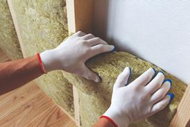
The roof is insulated with 500 mm of dry blown Warmacel cellulose insulation; while the external cavity walls use 300 mm of Rockwool insulation. The concrete floor planks rest on aerated concrete block dwarf walls. Sandwiched between the ground and the planks is 200 mm of expanded polystyrene and a layer of mineral wool to prevent cold bridging. The mineral wool should compress under the weight of the concrete planks, and thereby prevent free air gaps.
An earth berm against the north facade acts as an insulating buffer and also deflects cold northerly winds up and over the roof. Any negative pressure this may create on the roof’s south side will help to draw out ventilation air through the clerestory windows.
Recycled Rosemary tiles from local council houses were used on the roof. These discharge into oversized gutters, which, on the south side are wide enough to walk in and provide access to the photovoltaic and solar air array for cleaning and maintenance.
Internal layout
The 750 m2 building includes an exhibition hall, a café/restaurant, classroom and a residential apartment, which will house an educator/building manager at some point in the future when funds are available. The need to make the most of the passive solar gains has largely dictated the internal layout. As the classroom and restaurant are expected to have the highest occupancy during the daytime, they are situated on the south. The kitchen, toilet block and exhibition hall are on the north side, along with the main entrance. Above the restaurant, kitchen and toilet block is the space set aside for the residential apartment.
The designers are hoping for an airtightness factor of 5 m3/h/m2. In addition to the usual seals and vapour barriers for the doors and windows, significant quantities of mastic have been expended to seal penetrations and junctions. One advantage of the exposed masonry walls is that if any remedial action should be required after the pressure test, it will be possible without too much disruption.
Heating and ventilation
Space heating during the winter months is delivered using the minimum volume of air needed for ventilation. An air handling unit delivers warm air via low-level displacement units, the air is in turn extracted through ceiling-mounted grilles. A cross-flow heater allows recuperation from the outgoing air.
The design team looked to avoid internal summer temperatures above 28°C, but boundary conditions were very uncertain. It wasn’t clear what the exhibition space would hold, and what heat gains might come from it or any associated lighting. Occupancy was based on figures from local museums and exhibition centres.
During the summer months the centre will rely on natural ventilation. Cool air is drawn into the building at low level through vents and windows, and is heated by solar gains, occupants and appliances before venting through the clerestory windows. Wooden louvres adjacent to some of the window openings allow secure night-time ventilation. Each louvre has an insulated wooden door which, when open, allows air to enter and cool the building. The heat that is purged discharges from the clerestory windows and other vents.
Central heat store
At the heart of the centre lies the key to its efficient energy use. The Solvis central heat store provides a means to regulate the available heat energy between periods of high energy supply and demand. It effectively acts as a thermal battery, providing energy for the building’s space heating and domestic hot water needs.
The store is basically an insulated steel cylinder that holds 1500 litres of hot water at various levels depending on temperature. The four sources of hot water are: the ventilated photovoltaics/solar air collector; the evacuated tube solar hot water array; a dual-fuel boiler; and return from the air handling unit.
These are introduced via three input pipes that have outlet nozzles at various heights to enable stratification. As water enters the tank it discharges through a valve at the appropriate level corresponding to its temperature.
The 34 m2 ventilated photovoltaic array, the first of its kind to be installed in the UK, is operated in conjunction with the solar air collector. Air is circulated behind the panels to absorb the heat. The cooling effect that this has also helps to improve the photovoltaic’s efficiency, (which decreases by 0·4% for every 1°C above 25°C). This heated air is then passed through the solar air collector. This is designed specifically for heat to air transfer and consists of a layer of glass covering finned metal plate, behind which the air flows. The warm air passes through an air-to-water heat exchanger which feeds the central heat store.
The solar hot water system is made up of 120 Thermomax evacuated tube collectors. Heat is conducted from the absorber plate to a manifold situated at the top of the tube, where water is heated and pumped to the central store.
The dual-fuel boiler is the third main input for the central heat store. This can run on oil, although it is intended that wood will be the main fuel once the woodland is being managed and the coppicing demonstrations are underway. The boiler is fed by pre-warmed water from the return of the main heating circuit, while the return feeds into the hot water tank.
The two outputs for the central hot water store are the space heating and the hot water supply. Water is pumped independently from the top of the tank to the air handling unit and the hot water cylinder. The domestic hot water is stored at a low temperature (45°C) to save energy, and is uv-sterilised at the outlet of the hot water cylinder.
Regulating the thermal energy
The building’s thermal energy store is regulated by the temperature of the central heat store, the availability of energy from the solar collectors and the back-up boiler.
When a temperature of 45°C is reached in the heater battery of the ventilated photovoltaic and solar air collector array, a fan recirculates air, the heat from which is taken to the central store. When the store cannot take any more hot water, the pump to the tank is shut down and dampers open to dump the air into the atmosphere.
The solar water system is initiated when the water temperature in the manifold of the collector is 10°C higher than that of the central store. When no more heat is required, the pump for this collector is shut down and the tubes are left to regulate their own temperature.
A sensor at the top of the central heat store is used to turn on the boiler if it is needed. When the boiler has brought the temperature of the store up to 60°C, the system is set to operate the ventilated photovoltaic and solar array heater battery and the solar water system before the boiler is allowed to operate again.
Operating modes
The ventilated photovoltaic and solar air collector array has been designed with four modes of operation to optimise performance throughout the year. The main mode of operation during the winter is for the collector to act as a preheater for ventilation air. After air enters the collector it is heated to the required level for space heating by the cross-plate heat exchanger and the ahu. This also enables the heat exchanger to be bypassed if the pre-warmed air from the collector is of a higher temperature than the extracted air.
Second, during the summer, when unheated air is required, the collector is bypassed completely. A third mode entails heat from the collector being dumped into the atmosphere, when the heat is not required for use within the building but the photovoltaic modules need to be cooled to maintain their efficiency. The final mode involves circulation of air in a closed loop through the array and an air-to-water heat exchanger connected to the thermal store.
Water supply and usage
Collection of rainwater from the roof will be the primary water supply which is stored in a 20 000 litre grp tank buried behind the building. The water is coarsely-filtered before entering the tank to remove leaves. On leaving the tank it passes through a fine filter before being split into water for toilet flushing and potable water, which passes through a uv-steriliser. Based on the number of expected visitors and their anticipated water usage, it has been calculated that the building’s roof area should be sufficient for the water needs. However there is a mains water connection for three reasons: first, to cover the initial start-up period of the project; second, to meet any additional needs should demand outstrip supply; and third to satisfy health and safety issues.
To cut down on water usage, waterless urinals, 4·5 litre low flush wcs and spray taps have been used. A composting toilet is installed in the disabled toilet. The designers were keen not to imply austerity in the use of water, and instead demonstrated that there was enough water for normal use.
Both the grey and black wastewater and the liquid from the composting toilet are piped to a biodisk. This is basically a large chamber with a series of black corrugated disks stacked along a horizontal rotor that continuously turns, dipping into the contents of the tank. The surface of the disks is coated with a layer of aerobic bacteria that break down the effluent.
The liquid from the biodisk will flow out through an overflow into a soakaway. It is intended that the sludge will be used for composting around the parkland.
Consideration was given to recycling the grey water for flushing toilets but the extra complications and cost that this would incur led to the idea being abandoned. One unchartered territory is the effect that fluorine and other additives may have on the bacteria should a switchover to mains water be necessary.
Electricity supply
The intention is that the main sources of electricity will be supplied by the combination of the photovoltaics and the wind turbine. This will be split 4·1 MWh/y for the photovoltaic and 35 MWh/y for the wind turbine. Ideally, over the year the fluctuation of wind and solar energy will balance out, enabling the centre to be energy-neutral in electricity terms. A connection to the electricity grid has been maintained for back-up during periods when wind and solar generation are not possible. Any export electricity will be sold to the adjacent council-owned leisure centre. This neatly bypasses the inherent problems that often arise from selling electricity back to the supply companies.
The wind turbine will be situated at the higher southern end of the park, placing it in the jaws of two residential areas.
Compact fluorescent lamps have been specified throughout, and in some areas these are linked to daylight sensors. There will be a constant level of dimming through the building because of the uniform levels of daylight penetration.
The lessons start here
As part of a three year programme by the Institute of Energy and Sustainable Design, the building, its systems and outside environment will be monitored to provide data on the building’s energy performance and to optimise the systems. Internal temperatures, relative humidity, heat flux, the generation and consumption of electricity, water usage and the weather conditions will all be recorded and made available on the Millennium Park web site1.
The Millennium Park Environment Centre has the potential to provide a valuable and inspirational learning experience. It demonstrates some innovative technology and aims to show that sustainability doesn’t have to mean a drop in comfort levels for the users. The challenging part is still to come; the sequencing of the systems and controls, particularly the sources for the heat store, won’t be achieved overnight, and will add another chapter to the learning process.
Millennium Park Environment Centre, Oadby
Engineering dataGross floor area (gfa): 750 m2
Plantrooms: 30 m2, 74 m2
Restaurant: 179 m2
Exhibition area: 218 m2
Classroom: 74 m2
Conservatory: 51 m2
Accommodation: 136 m2 External design conditions
Winter: -4°C/Sat Internal design conditions
Winter: 19°C min
Summer (non a/c): 28°C max U-Values (W/m2K)
Walls: 0·12
Floor: 0·15
Roof: 0·09
Glazing – vertical: 1·16 - conservatory: 2·75 – clerestory: 1·20 – rooflights: 2·75 Structural details
Slab thickness: 200 mm
Floor to ceiling: 2900 mm
Live load: 3·0 kN/m2
dead load: 1·5 kN/m2 Occupancy
Visitors: 20 000/y Target energy use (gfa)
Wood: 5·2 kWh/m2/y
Electricity: 33·0 kWh/m2/y CO2
target: neutral or better Energy breakdown
Electricity generation – photovoltaics: 4·1 MWh/y – wind turbine: 35 MWh/y
Thermal capacity – solar water: 4·4 MWh/y – solar air: 8·1 MWh/y
Heating: 12·5 kWh/m2/y
Hot water: 8·9 kWh/m2/y
Fans & pumps: 7·7 kWh/m/y
Lighting: 2·2 kWh/m2/y
Fabric leakage: 5 m3/h/m2 @ 50 pa Loads
Calculated heating load: 9·4 MWh/y
Fan power: 2·8 W/litres/s
Lighting: 6·7 W/m2 Ventilation
Scheduled supply air temp: 27°C max
Room temp: 19 °C min
Fresh air: 100% with heat recovery
Filtration EU category: EU4 Primary air volumes
Total fan power: 3·3 W/m2
AHU at: 0·9 m3/s Distribution circuits
LTHW: 45°C flow, 35°C return – ahu heater battery
DHWS: 45°C flow, uv-sterilised Lighting
Types: Dimmable compact fluorescent
Lighting load: 5 kW
Efficiency: 2·2 W/m2/100 lux
Lux levels, Occupied areas: 300 lux Costs (millions)
Total cost: 0·90
Building services total: 0·175
Total net cost (£/m2): 1433
Mech services cost £/m2 (gfa): 100
Electrical services £/m2 (gfa): 133
Downloads
Ground floor plan
Other, Size 0 kb
Source
Building Sustainable Design
Credits
Client Oadby and Wigston Borough Council Project manager Oadby and Wigston Borough Council Architect Henderson Scott Architects Energy and environmental consultant Institute of Energy, Sustainable Development – De Montfort University M&E consulting engineer Environmental Design Partnership Structural engineer Stuart Morris Partnership Quantity surveyor AD Masic Mechanical contractor Star Building Services Electrical contractor John Unwin Building contractors Hallams Airtightness testing Building Sciences Photovoltaic commissioning Wind & Sun


