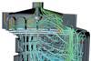
We explain how cfd software can help engineers ensure that their buildings are Part L compliant.
The revision of the Building Regulations Part L2 in April 2002 has led to a rethink on the design approach adopted on new commercial buildings in the UK. One of the main changes in the approved document is the introduction of a requirement to prove that the proposed building meets a certain carbon emission rating when compared to a notional building. This is in addition to other new issues such as limiting solar overheating in perimeter spaces.

These requirements are prompting designers to look for a more environmentally progressive design approach and consider the use of natural ventilation and mixed mode environmental designs.

For the majority of buildings, standard calculation approaches still provide a suitable means to analyse building performance. However, in certain buoyancy driven schemes, where stack effects or airflows are important in the ventilation design, a more detailed assessment would help optimise the performance to reduce carbon emissions and provide added credibility to the design. This is particularly true for cases involving rooms with high ceilings and large glazed areas.

One method, historically considered as an expensive luxury in building design rather than a necessary and invaluable tool of the trade, is computational fluid dynamics (cfd). Typically, this approach was only available to those companies with significant resources to construct and solve representative models within a realistic timescale such as in the automotive, process and aerospace industries.

However, advances in the affordability of high-powered computing, and improvements in the functionality and ease of use of commercial software mean that cfd is becoming standard in more industries and can now be considered as a valuable and practical design tool for analysing building performance.

Models can now be created in a matter of hours and solved overnight providing airflow characteristics within a simple 3D space quickly and relatively inexpensively. The results provide comprehensive information on flow velocity, temperature, humidity and any other required variable. This can be used to predict the occupant comfort levels within a building before construction has begun.

Getting started on producing a cfd study for a design is actually quite simple. The process begins with the 3D cad model, which can be supplied by the designer or architect in suitable format. If this is unavailable, the layout can be built from drawings using the geometry creation tools available in most commercial cfd codes.

Specifying boundary conditions
Having constructed or imported the geometry of the building design, the air filled space is broken down into hundreds of thousands of tiny cells generating a computational mesh. Each of these cells represents a point in space where all of the variables of interest will be calculated. The next step is to specify the boundary conditions that will describe the physics of the building, along with any appropriate models, eg for turbulence or thermal radiation. The boundary conditions specify variables such as flow rates at openings and heat sources from occupants and equipment. This calls for some sensible judgement from the user to determine the most appropriate inputs. Here, it is worth bearing in mind that cfd has a wide range of applications and the models selected should be physically representative and reflect reality.

The hard work of the user is then done and it is the turn of the computer to iteratively solve the equations of energy and fluid motion in each individual cell, taking into account the physical laws of conservation. When the solution has finished, the user can interrogate the results using the range of post-processing options to determine airflow and thermal characteristics of the building as a whole, or in local zones. This will provide an accurate and realistic virtual picture of how the building design will perform.

A variety of outputs allow the user to obtain any information they may need, whether graphical or numerical. Point data provides outputs comparable to conventional probes (such as at smoke detectors and airflow feedback controls). Average, minimum or maximum values of any quantity can be determined for the whole building or regions of interest, eg the average temperature and humidity in occupied spaces. Contour plots provide graphical output over a selected region, such as air speed within a slice of a room. Comfort criteria such as mean age of air, predicted mean vote and percentage of people dissatisfied within the microclimate can be calculated and plotted directly throughout the domain.

The use of advanced options enables the user to produce animations, such as the flow path lines from diffusers or walk-throughs of the geometry, allowing the designer to easily visualise the fluid flow physics at work. These are powerful ways of presenting the results back to those who do not necessarily have a direct involvement in the analysis work but who are influential figures in the building design and who will benefit from the information gained.

CFD is already being used to provide a competitive edge for those buildings seeking a more environmentally friendly approach and has already built a track record of success. CFD technology has been successfully applied to a range of applications including:

  • Atria, auditoria and sports halls.
  • Fire and smoke modelling to determine if mechanical smoke extraction is required.
  • Assessing car-park ventilation for exhaust and smoke extract.
  • Cleanrooms and contamination control for pharmaceutical and electronic manufacturing facilities.
  • Data centres and telecom switching facilities.
  • Offices and commercial premises.
  • Environmental wind analysis.

The shortfalls
Having outlined the extensive capabilities of cfd to address issues related to innovative building design, it is equally important to understand what cfd cannot do. CFD technology does not offer those involved in building design a panacea. Dynamic thermal modelling remains the best method for predicting how a building reacts dynamically with external conditions over a long period of time. Based on historical weather data, this analysis allows calculation of a building's thermal response, showing where and when peaks will occur and energy performance over a representative year. CFD plays a vital role in this type of analysis by providing data such as wind pressure coefficients at window openings if wind tunnel testing data is not available. However, for a comprehensive assessment of the thermal and airflow characteristics around and within the building at the times when normal or peak loads occur, cfd does offer a more comprehensive understanding.

In terms of practical usage, technical limitations remain – the capability of cfd remains restricted by the speed and memory size of any given computer. For large buildings that require complex models, a cluster of computers to solve the problem within a realistic timescale may still be required. However, current software allows standard desktop machines to be used in parallel to achieve the necessary performance. Also, as with all modelling tools, the results are only as good as the boundary conditions that are applied. Without the necessary experience it is therefore possible for an inexperienced user to generate a converged solution that is not true to life. This makes expert consultancy essential if a fully trained, experienced user is not available.

At this stage in the use of cfd technology within building design, many companies will not have the resource of a suitably trained engineer and so hiring the expertise offered by commercial cfd companies is the obvious alternative. This can be particularly economic if design compliance is required for a one off project within a tight timescale.

However, if there are numerous building designs that require compliance and a competitive edge is desired, then an in-house cfd capability allows the designers to obtain a detailed insight into the behaviour of the building physics that other designers may not have. This frees the designer to be creative, with confidence in their design, benefiting from a previously impossible insight into how their integrated building and ventilation design performs.