Not enough space, a tight budget, a large asbestos strip-out programme and poor record documentation aside, there was the need to maintain systems and develop a construction programme that would allow researchers and students to carry on working.
The chemistry department buildings were originally designed and built in the early to mid 1950s and comprise north, south and west blocks, surrounding a central area that houses lecture theatres and the atomic imaging laboratories.
Each of the blocks has a slightly different floor arrangement, an added complication when taking services from one zone to another. The north block comprises of basement to third floor, the south has basement to fourth floor and the west block is basement to fifth floor. There is also a south wing, basement to fourth floor and an east wing, sub-basement to fourth floor.
The structure is predominantly concrete frame with brick infill while in some areas the risers form part of the shear walls limiting the number of new penetrations that could be made.
Danish Architect Erik Sørensen, who designed the adjacent award-winning building for the crystallography department, drew up a comprehensive refurbishment strategy. Following this the Joint Infrastructure Initiative awarded £28 million to the department of chemistry for the refurbishment, with a further £2.5 million from the University to cover enabling works. Local architect Nicholas Ray Associates took over the project having previously worked with the university's estate management building services on the refurbishment of two laboratory areas within the building.
Scope of the refurbishment
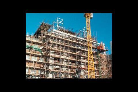
The project is ambitious and comprises an eight-phase programme over a three-year period. Oscar Faber were brought on-board to do the building services design for the entire JIF refurbishment, which started with the overhaul of the atomic imagining laboratories in December 1999 and is currently seeing phases three, four and five nearing completion. By September 2002 the project will have included the construction and refurbishment of around 10 000 m2 of laboratory space, the relocation of the central boiler plantroom, the conversion of the existing boiler house into workshops for the technical support services, building and extending rooftop plantrooms and the creation of a system of external ducts and flues. As well as this there is a major restructuring of the lv electrical supply, segregation of domestic and laboratory water supplies and installation of a new centralised treated water system.
Laboratory refurbishment
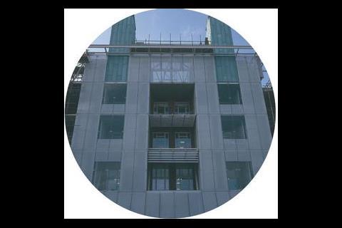
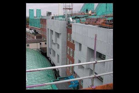
The biggest problem for project director Alan Fox and his design team was the lack of space for accommodating ductwork for the fume cupboards, which in some instances had increased ten fold to around 30 cupboards in an area of 400 m2. An external ductwork strategy was developed prior to the JIF refurbishment to free-up internal space. On the south block this has meant routing the extract ducts up the front facade of the building and similarly running the supply ducts down the back. The need to preserve the front elevation of the north block has meant that both the supply and extract ductwork had to be routed down one side. "This is a bold solution," explains Fox. "You're having to build a whole new structure on the outside of the building and putting ductwork externally means it needs to be weather tight and clad."
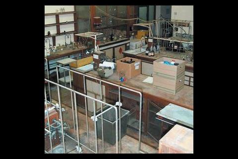
Laboratories are broadly split into teaching labs and research labs. Most incorporate 'write-up' areas but there is limited modularity from floor to floor.
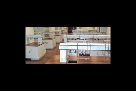
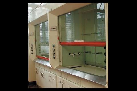
Taking the third floor south block synthetic chemistry laboratory as an example. Three groups of six prefabricated fume cupboards (two rows of three clustered back-to-back) are positioned at right angles to the south-facing windows. These are connected via Phoenix control valves to the common extract system serving each laboratory floor. All fume extract ductwork is made of pvc and wrapped in grp for improved rigidity and fire performance.
The general extract from the write-up and other areas is also connected to the common fume extract system via variable volume devices. Four fume extract fans are provided for each floor and are housed in rooftop plantrooms with the copper clad flue stacks terminating 7 m above the building roof.
To conceal the ductwork a glazed facade has been created 3·3 m beyond the original wall. As a result of the external ductwork strategy around half of the original window openings have been blocked in. Despite this the spaces still receive generous day lighting, helped partly by the new lower ceiling being offset from the full-height perimeter windows.
There are additional benefits of the new facade: "The shading provided by the depth of the service zone has helped to reduce solar gains," says project engineer Rob Green. "Which in turn improves conditions within the laboratories."
Each laboratory floor is provided with a dedicated supply air handling unit. However the shallow ceiling voids were a problem for the labs on the upper floors. "We were faced with the task of having a very dense fume cupboard layout, where we'd only have a ceiling void of 600 mm," explains Fox. "That really hadn't been thought about when they did the external ductwork concept."
The upper floors originally had floor to ceiling heights of 3 m, which was more than adequate when the building services were threaded through the trusses supporting the floors. However the university policy to improve fire resistance meant fire cladding the existing structure forcing the services to sit below the original ceiling.
The capacities of the ahu serving these floors are therefore constrained by the size of the ductwork that can be installed. Diversities on usage have had to be set up with the lowest around 60%.
Supply air is distributed by a low velocity ductwork system terminating in ventilated ceiling plenums in the laboratories and ceiling mounted diffusers in the write-up areas. Phoenix variable volume valves located in branch supply ducts adjacent to each laboratory will control supply volumes to laboratories.
Comfort cooling
There was a general policy not to provide comfort cooling for the laboratories, although provision has been made for the installation of cooling coils in the ahu – despite there being no immediate space for locating the chilling plant. The high air change rates will keep the laboratory air temperatures fairly similar to ambient in the summer. Cooling is therefore limited to the write-up areas and offices which are installed with cassette fan coil units using chilled water or dx systems using refrigerant R407c.
One of the specific pieces of equipment requiring process cooling was the scanning electron microscopes (sems). As Green explains: "Its location in the basement at the centre of the site is influenced by the need to keep vibrations to a minimum, beneath here is a substantial concrete foundation." A specialist cooling system was installed, designed to minimise vibration transmitted to the sems. A dedicated external chiller supplies chilled water to a water tank in the rooftop plant room of the south block, this is gravity fed to the sem before flowing to a water tank in the sub basement from where it is pumped back up to the rooftop tank.
The microscopes sensitivity also necessitated the installation of field cancellation coils in the atomic imaging labs to prevent interference from any magnetic fields.
Boiler plant room
Phase three of the JIF refurbishment involved stripping out the existing boiler plantroom in the basement of the east wing to make way for the technical services workshops. A mezzanine floor was inserted to create a basement and sub-basement to accommodate a range of support services including welding, soldering, glass blowing and electrical workshops. A previous lightwell on the north side has been extended out to maximise the daylight reaching the full height glazing.
"Again the main constraint is that you're working with an existing building with very small ceiling voids in which to route ductwork" says Fox. "Because of the processes they are doing in some of the workshops quiet a lot of air movement is needed." Supply air to these spaces is provided by a ground level ahu. Local extract ventilation is provided in areas such as the welding and glass-blowing workshops via articulated extract arms and recirculating filter units.
The mthw system has been replaced by lthw plant, which is located in a newly created rooftop boiler house above the existing third floor plantroom on the east wing. The distribution system has been totally re-engineered so that the four new 2·5 MW gas-fired boilers feed separate pumped circuits to different building zones, thereby improving the resilience of the system. Direct gas-fired heaters located at roof level provide hot water.
The original heating system used Frenger panels and embedded heating pipes on the basement and stair areas. "As we've had to strip the ceilings out we've had to review what the heating needs were" says Green. "Because there are large air change rates the heating of the laboratory spaces is generally by the air system. Heating to smaller spaces such as the write-up areas is via fan coil units, where the heating demand is expected to be relatively low.
Previously the mthw plant supplied steam for laboratory use; local electric steam generators now provide this.
Other laboratory services
Vacuum is provided by local electric under-bench diaphragm pumps that each serve up to six taps. This was considered to be more economical than the previous water jet vacuum systems (which relies on running tap water through a hose to create a vacuum). This used large volumes of water and led to the university installing a water recovery system that also recycles water from condensing processes. The system, which was estimated to save around 50% of the annual water bill, has been maintained and extended throughout the refurbishment. The existing high pressure and low-pressure water supplies have been extended to serve the refurbished areas. The existing treated water systems are being replaced with a new central system providing higher purity 'Analytical Grade 2' water to laboratory outlets.
A range of laboratory gases including argon, CO2, and oxygen serve the fume cupboards and benches, these are stored in local enclosures adjacent to each laboratory.
Electrics
The refurbishment has also seen a substantial overhaul of the lv distribution, which despite having the capacity was inherently inflexible with no logical distribution strategy. An upgrade in power was made to within the limits of the two original 1000 kVA transformers. The existing mains switchboards were reused plus additional switchboards introduced to give the capacity and flexibility required. Power has been distributed via the 1·5 m sub-basement crawl-way with a rising busbar system installed in the original risers.
Shut-downs have been difficult to arrange as many areas in the building need to maintain 24 hour operation. Durations of shutdowns have been minimised through detailed planning and simplified changeover operations where possible. Temporary supplies have been provided where required during the shutdowns within the capability of a 100 kVA generator provided by the University. These temporary supplies serve essential items of laboratory equipment such as fridges and freezers which must maintain conditions (temperatures as low as –80°C) to ensure the stability of certain chemicals.
Lighting has been standardised throughout the building with Category 2 recessed luminaires installed in the write-up areas. These are home to a large number of vdus so a general level of 400 lux has been specified. Category 3 recessed units are installed in the laboratory spaces. These are sealed clean room type fittings with prismatic diffusers providing IP65/54 rating to the room/ceiling sides of the units. Standard switch controls are used throughout.
The practicalities
The refurbishment of the Cambridge University chemistry department emphasises the problems encountered when upgrading older buildings and the complex planning needed in the phasing of the construction. The design team has had to minimise disruption to the department while maintaining a safe working environment and sequencing the work to take account of the continuity of the services.
The refurbishment is seen as essential in attracting new students and research. The building services will play a key role in achieving this goal.
University of Cambridge, Department of Chemistry
AHUs: Reycol
Boilers: Wellman Robey
Ceiling diffusers: Trox
Chillers: Carrier
DX systems (vrv): Daikin
Extract fans: Central Fans
Fan coil units: IMI
Fume Cupboards: Premier Air Systems
Pumps: Grundfos
BEMS: Trend
Electrical distribution: Group Schneider, MEM
Fire alarm/detection: Defensor
Luminaires: Whitecroft
LV switchgear: MEM, Group Schneider
Controls & motor control centres: Canham Controls
Power busbar: Barduct
Trace heating: Raychem
Total building floor area approx 20 000m2 – approx half of this refurbished
Parking: very restricted
Programme: Oct 1999 to Dec 2002
Form of contract: early phases JCT, later phases PC Works National Engineering Specification was used on this project with some additional clause, this is the Oscar Faber standard spec.
External design conditions
Winter: -3 °C db 100% rh (fabric heating)
-10°C db 100% rh (air handling systems)
Summer: 28°C db 50% rh.
Internal design conditions
Office/write-up areas 19°C min to 24°C db max no humidity control.
Staicase and circulation: 18°C min
Limited information was available on construction types. Poor U-values have been assumed for the purpose of thermal modelling/calculation. Generally, the original single glazing has been replaced with double glazed units to current Building Regulations standard.
Floor to ceiling: 3000-4000 mm
Ceiling zone: 600 mm
Net services zone: varies, min lab ceiling depth of 550mm
Offices/write-up: NR 38
Laboratories: NR 40-45
Plantrooms: less than 80 dBA
BREEAM: No
No specific energy targets were set. Generally, building energy use has increased due to the refurbishment as over 150 fume cupboards have been added resulting in a huge increase in ventilation and heating system loads. The new fume cupboards are generally variable volume, so greatly improving part load efficiency over the existing systems which were constant volume.
Calculated heating load: 6 MW
Installed heating load: 10 MW – includes provision for possible future refurbishment and standby capacity.
Installed cooling load: 320kW Office/write-up 15 W/m2, 25 W/m2 local max
Laboratories 25-50 W/m2
Solar gain not modelled in many areas as most of the building is not cooled.
Room temp: 19°C min, 24°C Max (office and write-up only)
Fresh air: 12 litres/s/per person min
Max recirculation: none
Filtration EU category: EU8
Total fan power: 350 kW (total approximate undiversified electrical load)
LTHW: 85°C flow, 65°C return
DHWS: 65°C flow
Chilled water: 6°C flow, 12°C return
Refrigerant: chillers R407c
2 x 1000 kVA transformers
kVA ups system – none
kVA standby power – see main text
Types: Category 2, Category 3 – IP65/54 rated Lux levels
Office/write-up/seminar: 400
Laboratories: 500
Toilets: 200
Plantrooms: 150
Circulation areas: 300
Total cost: £33 m
Building services total: approx half of total cost
Phase by phase
Downloads
Ground floor plan of the chemistry department
Other, Size 0 kbSection through the north and south blocks
Other, Size 0 kb
Source
Building Sustainable Design
Credits
Client University of Cambridge Project manager Cambridge University Estate Management & Building Services Architect Nicholas Ray Associates (original strategy Erik Sørensen/Zibrandtsen Arkitekt) M&E consulting engineer Oscar Faber Structural engineer FJ Samuely & Partners Quantity surveyor Northcroft Main Contractor AMEC M&E contractor Crown House Engineering


