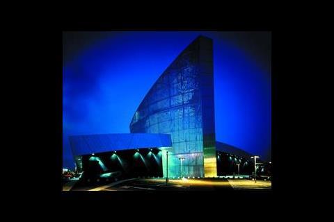
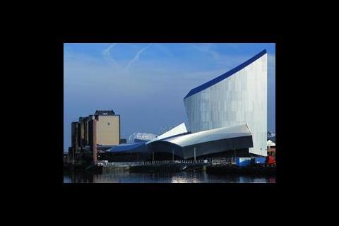
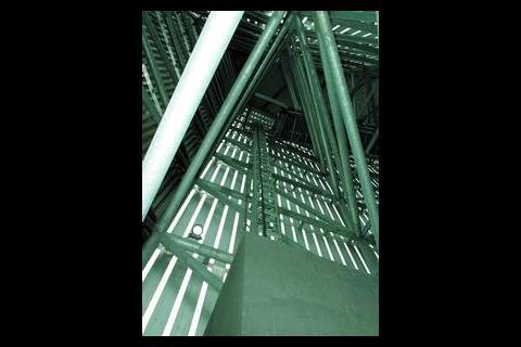
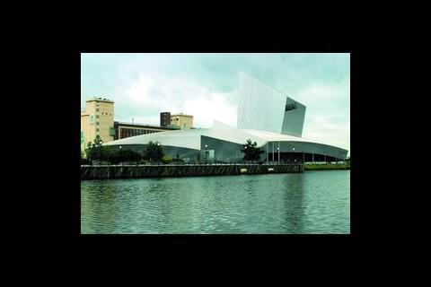
The earth and water shards share a similar structure of concrete frame up to the first tier with a steel frame roof support clad in aluminium panels and a standing seam roof. In contrast, the air shard is simply a galvanised tubular steel frame clad with narrowly spaced aluminium sections and as such is open to the elements.
Time and space
Discussions for the Imperial War Museum North (IWMN) began in March 1996 and the following year Trafford was announced as the preferred location. Property developer Peel Holdings donated a two-hectare brownfield site and also contributed £10 million towards the £30 million project cost. Other funding came from the Trafford Metropolitan Borough Council, the European Regional Development Fund, English Partnerships/North West Development Agency and the Imperial War Museum Trust.
The scheme was divided into two phases, the base build which began on-site in January 2000, followed by the £2.5 million fit-out. Consultants Connell Mott MacDonald were appointed to carry out the m&e development for both phases, working in conjunction with Studio Daniel Libeskind, associate architect Leach Rhodes Walker and structural engineers Arup.
The museum comprises two galleries, the main exhibition space and the special exhibition. Both these galleries are windowless and each reflects the external architecture with domed floors and ceilings – the 'north pole' of the floors and ceilings are offset creating massive gallery heights of between 3 m and 12 m.
The main gallery houses five large exhibits including a Harrier Jump Jet, and six separate self-contained display areas, or silos. It also contains the Big Picture, a 360° audio-visual show. Sixty projectors display 1500 slides during each 15-minute show, projecting continually changing images onto the gallery walls, floor and visitors, to 'create a totally immersive environment'. Next door to this is the smaller special exhibition space, which is designed to take a changing programme of exhibits.
Serving strategy
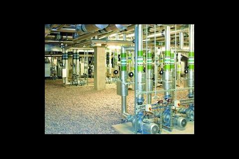
Flexibility was high on the agenda for the design of the exhibition spaces. The initial plan to locate the two main galleries on the ground floor was promptly shelved in favour of relocating them to first floor level. This had two advantages, one it would allow all plant to be located in a pair of plantrooms beneath the galleries, thereby reducing the complexity of servicing the exhibition areas. The second was cost, the site is a former diesel storage yard and as such much of the soil is contaminated, elevating the gallery spaces and putting the plant at ground level avoided the need to dig out a basement and dispose of the soil. The plant rooms are effectively external spaces enclosed on the sides by louvres; equipment is simply installed on concrete plinths with stone chippings used to conceal the surrounding ground.
Internal design temperatures in the main exhibition space range from 18°C to 26°C, with special exhibits housed in their own environmentally controlled cabinets. A mixed-mode ventilation system supplies air via a low-level displacement arrangement comprising a grid of custom-designed outlets installed across the floor slab, supplemented by outlets concealed around the base of the silos. The system suits the high spaces and tests showed the outlets would achieve winter and summer penetration of about 12-15 m. The continuous traffic in the space is also a bonus, "the whole process is helped by the movement of people who assist in moving the air around," says Tim Blissett of Connell Mott MacDonald.
In the natural mode dampers linking the gallery to the ventilated plant room beneath are opened along with a damper connecting the gallery to the air shard, and natural stack effect drives the system.
When external conditions are unsuitable or internal conditions demand tempered air is supplied via plenum boxes feeding the same custom-designed outlets. In the summer either the carbon dioxide detectors in the gallery or the internal temperature sensors can initiate the supply air which is delivered, dehumidified and reheated to 18-22°C, at a volume dependent on the load required and the internal temperature. Extract is at high level through slots on either side of the light troughs to the ceiling air plenum and then out via the Air shard.
Background heating and comfort cooling is supplied by over 2 km of pipework embedded in the concrete floor slabs; this is split into two zones for the main exhibition area, one for the special exhibition and one for the restaurant/café in the water shard.
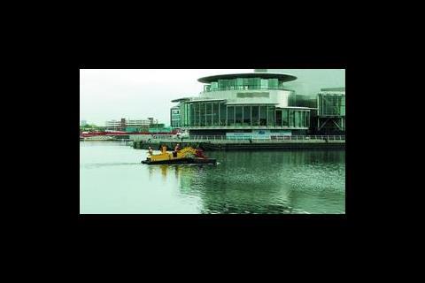
With the windowless spaces there is a blur between the heating and cooling seasons with the potential for cooling to be needed year-round. Like the neighbouring Lowry centre, the IWMN makes use of the adjacent Manchester Ship Canal to provide free cooling, in this case via the floor slabs which can also be cooled using mechanical refrigeration if required.
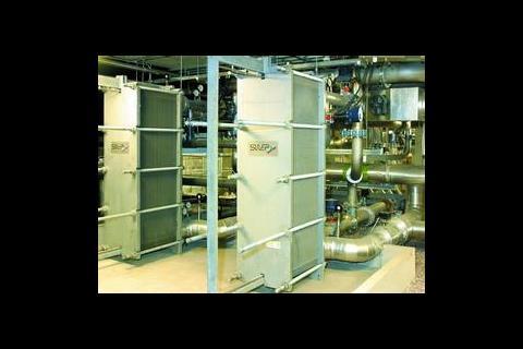
The temperature of the canal water is typically around 10°C in winter and 17°C in summer, although records show some higher (22°C) and lower temperatures (5°C) in extreme years. Unlike The Lowry the IWMN uses a much larger (1 m diameter) extract pipe to reduce the face velocity of the incoming water to avoid drawing-in excess sediment from the canal. Water is pumped through two sets of filters, before passing through a heat exchanger. Temperature sensors ensure that the temperature rise of water between inlet and outlet is limited to 5°C.
Canal water also supplies primary cooling for the chillers. "Condenser water is provided via an injection system from the canal cooling at 22°C which gives an uplift in cop of about 25%," explains Blissett. Pre-cooling for the ahus was also considered but with a payback period of 50 years it wasn't deemed viable.
Winter losses in the main exhibition space are offset by the underfloor heating and tempered air supplied through the low-level displacement system on demand from the quality sensors. Heating loads are smaller than for a conventional building, about 20 W/m2, and are provided by three 600 kW high efficiency gas-fired boilers.
The special exhibition gallery has been designed to take potentially sensitive exhibits, and under the guidelines set down by Re:Source (Council of Museums, Archives and Libraries) is fully air conditioned with internal conditions of 22°C ±1·5°C at 55% rh ±5% rh. The space has a dedicated ahu that provides the heating and cooling on the airside through a grid of floor diffusers, with high-level perimeter extract. This unit is also fitted with a dx system and connected to a 250 kVA back-up generator to maintain conditions in the event of a power failure.
Audio visual and main gallery lighting
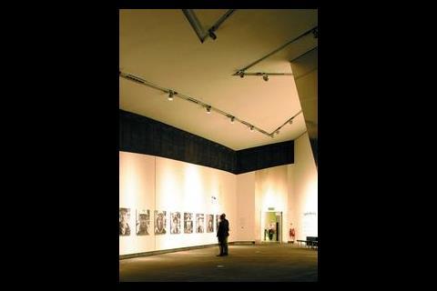
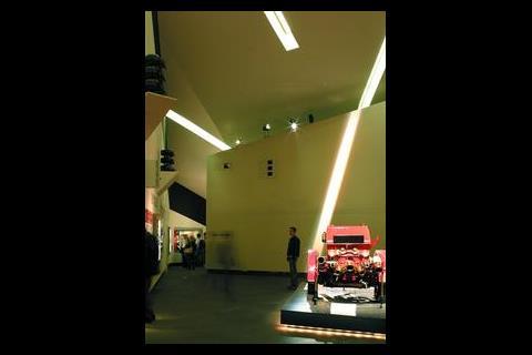
Throughout the museum the lighting has been designed to harmonise with the architecture. In the main exhibition space the design team worked to a background lighting level of around 75 lux or 100-150 lux with display lighting. "This is a good figure for a museum," explains David Eastland, associate with Connell Mott MacDonald. "What you are trying to do is light the objects not the space, the brightest object on the wall is what you will be drawn to." With such a dynamic space, modelling was difficult and Eastland says the lighting has a lot to do with anticipation and feeling.
Conflicting, irregular lines of light troughs are stamped out across the ceiling. The position of these initially followed a plot of the sunpath as it moved over the ceiling. "Libeskind's liked the idea and adapted it, taking parts of the curves and mixing it with longitudinal lines and extra curves to produce the angular, irregular pattern," says Eastland.
The light fittings are fluorescent units with opal diffusers, custom-made by Taison lighting to form a continuous light line within a deep builderswork plasterboard trough. The troughs are 400 mm wide and 800 mm deep – which also provide the return air path to the ceiling air plenum. The light fitting was designed to minimise dark spots on the opal diffuser at adjoining lamps by maximising the distance of the lamp from the diffuser, simple but effective.
Other methods were tried such as overlapping lamps and using reflectors but the simplest solution was to make the box deeper and take lamps away from the diffuser's surface to make it less pronounced.
Tridonic digital ballast gear dims the house lighting down very slowly when the audio/visual show begins, reducing the light to about 3-4% before it cuts out. Eastland explains that they were reluctant to apply for a cinematic license for the audio/visual show in the main exhibition gallery. "This would require there to be background lighting to prevent the room being plunged into darkness should the projectors fail." This meant convincing Building Control that the space was safe with no light on at all. If during show mode there is a power failure the emergency lighting would come on, and there wouldn't be a problem. Safety issues arise though if the show cuts out when the mains supply is healthy. "We looked at automatic controls and sensors but no matter what you did there was a level of complexity involved which was potentially fallible," says Eastland. Instead the system relies on a simple white break glass on the wall, if the show blacks out for whatever reason or there is an emergency the glass is broken, the show stops and the house lights come on.
Emergency lighting works off a central battery system to preserve the clean lines of the ceiling. Telltale holes are the only evidence of the VESDA fire detection system that was installed to combat the height of the space and also for maintenance reasons – it's also installed in the void, as there is no access through the ceiling.
The lighting for the silos and the exhibits was carried out by a specialist, this followed the electrical scheme and was prone to change. Rather than second-guessing what would be required in terms of wiring or data cabling, termination boxes have been installed which provide numerous control zones and remote locations for connecting the display lighting when the design was complete. These have proved more than adequate.
All the m&e services for the exhibition spaces are fed from below to the walls and to maximise flexibility 300 mm diameter mechanical and electrical service holes have been built-in around the structural columns. Soft spots have also been designed into the floor to allow for future changes in layout. These comprise a 600 mm plug that can be jacked out from the plant room beneath and, with a little remedial work to the asphalt flooring, used to create a new air diffuser or electrical socket.
Special gallery and other lighting
A track-based lighting system has been installed in the special exhibition gallery – trough lighting similar to the main exhibition gallery was rejected because of the constantly changing exhibits and cost – which uses Erco aluminium luminaires with metal halide lamps. Again the ceiling and floor are spherical but to a lesser degree than the space next door. The layout of the track is dependent on the height of the space and the line of the wall – this is to achieve a 30° angle of incidence to prevent putting shadows on pictures/photographs displayed on the walls. In plan this gave a line winding around the perimeter, which Libeskind tweaked to give a more abstract pattern. "It worked for me functionally as an engineer and it worked for the architect as a form," says Eastland. Similarly the emergency lighting is incorporated into the track system. Every 3 m a 300 mm length of track is wired separately into the central battery system, maintaining the overall appearance of the continuous track.
Both the restaurant and the entrance area also make use of fluorescent fittings. In the entrance long unobtrusive troughs are cut into the plasterboard ceiling, which house standard fluorescent fittings concealed behind robust, metal floor gratings – at the architects request – which hang flush with the ceiling.
By day the air shard looks like a solid element but at night it is transformed by internal lighting. Two sets of Thorn contrast metal halide floodlights are installed, one set of six 150 W units direct light down to the floor from a height of 10·5 m, while a second set of 250 W units are angled upwards. Additional 250 W units are installed along the walkway to the observation platform, boosting the light out of the top, giving a cool clinical light to show off the steelwork.
Those fit enough and with a head for heights can reach the viewing platform by the stairs. However there is also the option of the lift, which is basically a rack and pinion construction hoist with a bespoke surround. This was chosen partly because it is inclined from the vertical in two perpendicular planes of 6° and 3°. "Our only other option was to provide a traction lift. That would have meant putting a bigger concrete core up, filling it with lift kit, finding room for a motor room and at the time we wanted to save money," says Eastland. "And also the architects liked the look of it."
With the approval of Re:Source security, lighting and cctv systems were designed in a strategy of rings of defence starting at the perimeter fence moving inwards and finishing at the display cabinets.
The future
The IWMN is the latest step in the regeneration of Salford Quays and the design team have exploited the site – taking advantage of the Manchester Ship Canal for cooling – and neatly side-stepping any complications the contaminated ground might have held. Despite the museum's innovative shape it has been completed within a tight budget, reduced from £40 million to £28.5 million, by keeping the building technology simple and using standard materials adapted to suit the design. This belies the work that has gone into the design; the lighting may look very simple and unobtrusive but to achieve this took time and coordination.
The same care has been extended to other areas of the building not open to the public. Over £90 000 was invested in creating a 3D model of the plantrooms to identify any clashes between service runs, prudent given the geometry of the spaces. And, given that these sit directly below the domed floor slab of the exhibition halls, installing overhead pipe runs wasn't as straightforward as the ordered layout might suggest.
Ultimately the success of the museum will be measured in visitor numbers. In just over five weeks since opening to the public it has welcomed its 100 000th visitor, already a third of its annual target.
Imperial War Museum North, Trafford Wharf Road, Trafford Park
Mechanical suppliersAHUs: Barkell
Air curtains: Thermoscreens
Anti-vibration mounts: Engineering Appliances
Boilers: MHS Boilers
Ceiling diffusers: Schako
Chillers: Aiax
Control valves: Trend
Computer room a/c: Daikin
Dampers: Actionair
Ductwork: W T Fabrications
DX systems (vrv): Daikin
Extract fans: Woods
Expansion bellows: Engineering Appliances
Floor grilles: Schako
Flues: Flu-Stax
Heat exchangers: Baltairco
Hot water calorifiers: Rycroft
Humidifiers: Vapac
Insulation system: M ductwork T W Insulation
M pipework T W Insulation
Louvres: Architectural Steelwork
Pumps and pressurisation: Holden & Brooke
Radiators: Hudevad
Sound attenuation: Sound Attenuators
Strainers: Oventrop
Tanks: Robust
Toilet extract: NuAire
Underfloor heating: Warmafloor
Water treatment: IES
Valves: Oventrop
Water boosters: Holden & Brooke
Water heaters: Andrews
Electrical suppliers
BEMS: Nobbs & Jones
CCTV: ADT
Cable management: Mitre
Controls: Nobbs & Jones
Electrical distribution: Rappell Switchgear
Electrical accessories: Caradon MK
Fire alarm/detection: ADT
Floor boxes: Wiremold
Internal lifts: European Lifts
External lift: Alimak
Lighting controls: Clipsall
Luminaires: Taisson Lighting
Floodlighting: Thorn
LV switchgear: Groupe Schneider
Motor control centres: Rappell Switchgear
Standby generation: Musgrave
Trace heating: Raychem
Voice alarm/public address: ADT
Engineering data
Gross floor area (gfa): 7000 m2
Plant rooms: 3000 m2
Offices: 900 m2
Amenity & dining: 750 m2
Contract details
Tender date:October 1999
Tender system: two stage
Form of contract: GC works
Contract period: m&e 16 months
Was National Engineering Specification used on this project: Electrical
External design conditions
Winter: -5 °C/Sat
Summer (a/c): 26°C db, 19°C wb
Internal design conditions
Winter: 22°C min, 40-70% rh
Summer (non a/c): 18-27°C
Summer (a/c): 22°C, 50% rh
Circulation & toilets: 27°C max, 18°C min
U-Values
Walls: 0·35 W/m2K
Floor: 0·15 W/m2K
Roof: 0·25 W/m2K
Glazing: 1·8 W/m2K
Structural details
Slab thickness: 300 mm
Floor to ceiling: varies
Ceiling zone: varies
Net services zone: various ceiling depths and through the floor and walls
Occupancy
Offices: various, 1 person/10 m2
Meeting rooms: various
Target design energy use (gfa)
Gas: 433 kWh/m2/y incl catering
Electricity: 243 kWh/m2/y Energy breakdown
HVAC: 109 kWh/m2/y
Small power: 16 kWh/m2/y
Lighting: 118 kWh/m2/y
Typical occupied hours: 56
BREEAM rating: no
Loads
Gross building load: 90 W/m2
Floor average: 90 W/m2 max
Equipment: 60 W/m2
Lighting: 21 W/m2
Distribution circuits
LTHW: 82°C flow, 71°C return
DHWS: 60°C flow
Chilled water: 5·5°C Refrigerant
Chillers: R407C
Computer room: R407C
Electrical supply
1 x 800 kVA Norweb transformers
250 kVA standby power
Lighting
Design lux levels due to lighting design uniformity is varied in many areas
Office: 500 lux
Kitchen: 500 lux
Toilets: 100 lux
Stairs: 100 lux
Circulation areas: 100 lux
Museum: 20 lux to 200 lux
Costs
Total cost: £27.3 million base build and fit out
Building services total: £3.4 million
Downloads
Plan of the gallery level layout
Other, Size 0 kb
Source
Building Sustainable Design
Credits
Client Imperial War museum North Project manager Gardiner and Theobold Management Services Architect Studio Daniel Libeskinnd Associate local architect Leach Rhodes Walker M&E consulting engineer Connell MottMacDonald Structural engineer Arup Civil engineer Connell MottMacDonald Environmental Engineer Connell MottMacDonald Quantity surveyor Turner and Townsend M&E contractor N G Bailey & Co Commissioning contractor N G Bailey & Co






No comments yet