Naturally, the Pasteurs and Boyles of the 21st century want neither the discomfort nor the risk faced by their forebears. A modern research building must be comfortable, efficient, and, most importantly, safe. The only mould here should be the contained form used in experiments.
The University already owned a suitable site half a mile west of the town – a prominent greenfield site overlooking St Andrews' famous golf course. Inevitably, the new building will appear on small screens everywhere when the British Open next goes to St Andrews.
Equally important for planners was the fact that the Bishop of St Andrews and other local bigwigs lived behind the building and disliked it. They sparked an uproar in the town's press – taking offence because it obscured their views of the beach and golf course.
The project team was formed in 1996, with Balfour Beatty as management contractor, Boswell Mitchell & Johnston as architect, and the David Elder Partnership designing services. There was no design competition but, as David Elder partner Robert Hopkins ruefully reported, consultants were appointed on competitive fee bids.
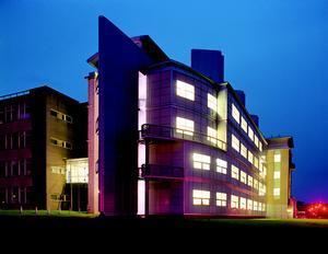
The building was completed in the spring of 1998, and occupancy began in May that year. The building's axis runs east-west across the site, connecting with the existing chemistry building to the south via a footbridge. Most of the north facade is glass curtain walling, with heavier blockwork on the south side and around the offices in the west wing.
Job architect Maggie Barlow explained: "We wanted a high-tech facade for the research areas, with more traditional blockwork for other parts of the building." Smaller windows on the south, east and west sides keep down solar gains, while larger windows to the north give the labs stunning views over the golf course.
The windows have conventional double glazing – mostly sealed units for the labs, with opening versions for offices. Pilkington K glazing has been used on the north-facing windows, while the company's 'high performance solar' glass was selected for the other sides. This compensated for the original plan to fit external shading on the south side, which had to be sacrificed on cost grounds.
A gantry at the eastern end of the building provides storage space for the specialist gases used on each floor. What could have been an eyesore was actually turned to advantage: aluminium composite cladding transforms it into an architectural feature, and the gantry is arguably the most attractive portion of the building.
The architects tried to avoid using hcfc-blown insulation – specifying Rockwool where possible. The one exception was in the plantroom roof, where Polyfoam was used. Here, watertightness was essential to protect equipment.
Overall, though, the building's environmental bona fides are not carried through to the building fabric: it only meets the minimum insulation values of the old Building Regulations. The curtain walling system contains a lot of aluminium – one of the highest embodied energy materials. However, architect Barlow said exceptional circumstances precluded other materials.
The architects were excited by the opportunity high fume stacks offered. "We articulated the flues to break up the skyline – something we were very keen to achieve," said Barlow. The bold enclosures certainly do that, and add visual interest at high level.
There was no written brief for the building. Instead, three professors (effectively the heads of department) briefed the consultants face-to-face. Although Hopkins felt positive about briefing at completion, it emerged that at times it had been a pretty bumpy ride (see 'A zigzagging path to the right building').
Surprisingly, given St Andrews' current profile on the environment, the University showed limited interest in energy or environmental issues. Indeed, initially the client wanted a fully air conditioned building.
Capital costs were all-important, not least because the University had raised 100% of the finance itself. The building cost £7 million – 20% more than was originally allocated. There were clear reasons for the upward drift in costs, though.
Through the doors
Visitors to the building are greeted by an arresting blue-walled entrance space, given sparkle from a score of metal halide downlighters. It is equipped with a smart designer reception desk that is a touching lesson in academic efficiency. Instead of someone being employed to greet visitors and tell them where to go, a printed sheet broadcasts staff extension numbers, to be reached on the telephone alongside it.
This high-technology, low overhead welcome for visitors is supplemented by a talking lift: it tells you what floor you're on and when the doors are closing. Unless, of course, you choose the more energy efficient mode of transport between floors – the stairs.
The building is on five levels: floors one to four house laboratories and offices, while the fifth floor is given over exclusively to plant space. The occupied levels are broadly divided into labs to the east, offices to the west.
Each floor measures 1082 m2– two-thirds of which is dedicated to lab space. Floors one and two have services in the mould of many other modern laboratory buildings: lots of clear bench space, with only a few fume cupboards. Floors three and four are chemistry labs, and level four offers a generous balcony overlooking St Andrews' Old Course. Not hard to imagine the chemistry professor here, sipping Pimms on a warm summer evening, watching the golf after a hard day's research.
The building was designed for 140 researchers – sometimes working late into the night and at weekends, which means the air handlers must work 24 h, seven days a week.
Airy, safe, efficient
The office accommodation is part natural ventilation, part mechanical. Areas with a low occupation density use opening windows and trickle vents, while more intensively used spaces have mechanical ventilation.
In essence, fume cupboards are this building's raison d'être. A fume cupboard is where white-coated occupants set up their experiments, closed off from the rest of the workspace by sliding panes of glass. In conventional laboratory buildings, a constant pressure fan supplies air into the lab, while another constant speed fan draws air from the fume cupboards.
As a result, the air change rate is very high (for this building up to 48 ac/h), even if the fume cupboards are not being used. This incurs a big energy penalty – not just to move the air into and out of rooms, but also to heat or cool it.
This building, though, tears up the rulebook for standard laboratories. It supplies only the amount of air needed to clear the fume cupboards that are open, varying fan speed accordingly. How? Electronic sensors measure the position of every fume cupboard hood. They relay this information to a Phoenix valve on the supply ducts in the plantroom.
This intelligent valve tightens as fume cupboards are closed – allowing less fresh air into the lab. The air handling units, in turn, sense the build-up of pressure as progressively more and more fume cupboards are closed, and wind down so that less air is pushed through whichever part of the building is affected.
On top of this, designers sized the mechanical plant for just half of all fume cupboards being open at a time. This recognises the reality that all researchers are unlikely to adjust their experiments together. It also saves running costs, the capital cost of plant, and the space requirements of the mechanical equipment.
Fresh air enters the building on the south side – through grilles leading to plenums in the plantroom. It is blown down the building to supply air to each floor. Extract air is then sucked back up to the plantroom before being ejected through the stacks, with general office extract leaving through roof-level louvres.
Each storey has an independent air handling unit (ahu). The ahus for the third and fourth floors split the lab air supply and extract from that for offices and reading rooms. A constant volume box ensures that the offices and reading rooms have the air they need all the time, while the air supplied and drawn from the labs varies to match fume cupboard needs.
Similarly, on the extract side, the ahus are controlled to pull only the minimum amount of air up through the building for releasing through the stacks. This minimum (8 ac/h) was selected to keep the air fresh even when the fume cupboards are all closed.
There is, of course, a minimum discharge velocity for the stacks – 10 m/s ensures fumes get clear of the building. Another clever engineering system maintains this minimum velocity by drawing in unheated outside air to mix with the fumes and feed through the stack.
The last piece of the low energy jigsaw comes in the shape of a large display panel showing the lab manager which fume cupboards are left open at any time. Light-emitting diodes give a very quick and easy check of who has forgotten to draw their hood at the end of the day – something that would otherwise jeopardise the labs' low energy performance.
A warm retreat
With cold winters and strong gales coming in off the North Sea it's a wonder golf is so popular in St Andrews. Important to know, then, that researchers can retreat into a well heated environment after a round.
CIBSE's recommended external design temperature is -5°C for this latitude. Heating comes from three boilers located in the western end of the plant level – partitioned off from the rest of the services equipment.
Having considered condensing boilers at concept design stage, the engineers found that ordinary atmospheric boilers would be more effective. The Hoval boilers they specified had to be meaty enough to cope with a huge volume of air – they are rated at a maximum 1·8 MW output, with gross efficiency claimed at 81%.
Grundfos variable speed pumps deliver just enough hot water to heat the air passing through the air handlers – modulating speed to match the valve position on the ahus. Likewise, for the radiant ceiling panels in labs and radiators elsewhere, the pumps adjust the water flow as their thermostatic valves shut down.
The coils in the air handlers have two port control valves instead of the usual three. This, again, helps to make the fresh air heating as efficient as possible – critical for this building because of the high air change rate.
Supply air is partly warmed by heat recovered from the general office extract. Run-around coils in the air handlers trap and apply this waste heat. The engineers investigated recovering the heat from contaminated air passing through the stacks, but experience from a government-owned building in Sheffield suggested this was not feasible. There, the corrosive effect of the fumes dictated the use of glass, which proved ineffective as a run-around coil.
Cool-headed research
The professors wanted writing areas outside the labs – so researchers can be sure of notes without iodine stains all over them. The architect arranged the laboratory wing with labs to the north, and smaller cellular writing rooms to the south. This way, the high heat loads generated from certain experiments do not add to solar gains from windows to the south.
In fact, the engineers do not anticipate overheating problems. As Hopkins noted, "St Andrews doesn't have summer temperatures like Kent." Ventilation alone is reported to keep the labs and offices cool even in summer. Admittedly, though, the two summers since completion were not hot (only "a few hours above 23°C" said the engineers) and the building was not fully occupied, which cut internal gains.
There are seven specialist areas where equipment with high heat loads needed mechanical cooling. These areas are cooled using packaged split systems from Mitsubishi – smallish units, rated between 3 and 6 kW.
The engineers accepted that this is not the most efficient system. A centralised cooling system with heat recovery, they said, would have pushed capital costs beyond the available budget.
Several coldrooms have freezers cooling to the extremely low temperatures needed to freeze samples. Here the freezers dump their rejected heat into the room, and the packaged split systems transfer this heat energy outside – effectively cooling twice over.
Fitting in the plant
The fifth floor plantroom is divided into two (see figure 1): air handling equipment runs the length of the building to the south, while the north-west corner is partitioned off as a boiler house. The remaining third of this floor, to the north, is open to the elements. This is set aside for three 1·8 m high fans drawing air up through the building, discharging through stacks that rise another 3 m higher.
St Andrews' Estates and Buildings staff joke about using the vacant space on the roof by the stacks to view the next PGA golf competition. They're rumoured to have deckchairs stashed discretely so they can make themselves comfortable on the roof. (If it's half as windy as it was when the author visited, they're not to be envied.) The electric distribution is straightforward. The existing 11 kV radial feed was upgraded to a ring main, which enters the building on level one in the south-east corner. The power upgrade wasn't in the original brief, and it naturally bumped up costs a little. However, a secure power supply is important for this building: to preserve frozen samples in the coldrooms, and, more importantly, to ensure researchers don't choke on fumes from their own experiments.
The standby power generator, pencilled-in at concept design stage, was dropped for cost reasons. Instead, the engineers put a plug-in point at the rear of the building for a portable generator. This could only serve the freezer room, though, and not the building's ahus.
The engineers specified sub-meters for electricity, gas and water, which was the client's preference. However, the original plans to fit a lighting control system had to be scrubbed to cut costs – the university then seemed sceptical about the energy benefits of a lighting control system. Nevertheless, the lighting is zoned, and researchers can control lighting locally.
There is no full-time energy manager monitoring this building, which makes it difficult to keep track of consumption. The current university-wide energy manager, Graham Niven, thinks the meters are a mixed blessing. "It's all very well having meters," he said, "but we have to read them." He's only been able to monitor gas consumption, and doesn't have staff with the time and expertise to read a modern electricity meter: "They [his staff] tried to read the meter for the first time last week, and they nearly had kittens – it's too sophisticated." Niven is unable to calculate the energy use from bills because the ring main is shared with 12 other buildings, not all of which have their own electricity meter. In fact, Niven is sceptical about the building's energy performance since completion. In his words, "the lights are always on but there's nobody in there".
No energy target was set for the building during design. With such a variety of uses in lab buildings, it's true that benchmarking is very difficult. The Building Research Establishment offers median values for energy use taken from a survey conducted in the early 1980s. These values are reckoned to be showing their age. The BRE's Colin Lillicrap says they are indicative only, and "modern labs should be less than half these figures".
BMS's 1998 gas consumption compares favourably with the survey median (476 kWh/m2 against BRE's benchmark of 669 kWh/m2), but does not meet Lillicrap's tougher objective of halving it. The engineers say that the benchmark data does not recognise the concentration of fume cupboards in this high-tech building.
Glasgow University's 11 600 m2 chemistry building may be a fairer comparison. Here, there are 100 fume cupboards (3/5 of the BMS density per m2), and annual gas consumption is 347 kWh/m2. To put this into perspective, the Glasgow building uses 279 kWh/m2 of electricity.
Regrettably, until St Andrews University is able to measure the BMS's electricity consumption, it is not possible to give a fuller impression of energy efficiency. Here lies the crux. Intuitively, the engineers' low energy fume-venting design must be saving energy. The sophisticated energy management system ought to be a good thing. However, without effective building management – correctly trained and resourced – there can be no guarantee of long-term energy efficiency.
Bio-molecular Sciences (BMS) Building, St Andrews University, St Andrews
Design conditionsExternal
Winter: -5°C/Sat
Summer (a/c): 25°C db, 19°C wb
Internal
Winter: 20°C min,
Summer (a/c): 21°C
Circulation and toilets: 18°C min U-values (W/m2k)
Walls: 0.45
Floor: uninsulated 200 mm ground slab
Roof: 0.3
Glazing: 1.8 (north facade), 1.6 (other) Noise levels
Offices: NR35
Toilets and circulation: NR40
External breakout limits: NR40 Energy targets
None
BREEAM: No Loads
Calculated heating load: 1.5 MW
Installed heating load: 1.8 MW
Calculated cooling load: 52 kW sensible
Fan power: 0.8 W/litre/s, 9 W/m2
Lighting: 9 W/m2 Ventilation
Scheduled supply air temp: 19°C
Fresh air: 100% in labs
12 litres/s/person minimum in offices
Filtration: EU3 and EU5 Primary air volumes
Floors three and four labs ahus: 20 m3/s
Floors one and two labs ahus: 10 m3/s
Offices ahu: 3.4 m3/s
Seminar ahu: 0.88 m3/s Distribution circuits
LTHW: 82°C flow, 71°C return
DHWS: 60°C flow, 55°C return Electrical supply
1000 kVA transformers Lighting
High frequency fluorescents, low energy downlighters Lux levels
Office: 500
Seminar: 300
Computer: 300
Toilets and stairs: 150
Circulation areas: 150
Efficiency: 1.8 W/m2/100 lux (labs)
Glare index: 19 Lifts
16 person, 1 m/s Costs (£ millions)
Total cost: £7
Building services total: 2.8
Total net cost (£/m2 tfa): 863 Main m&e costs (£’000s)
Mechanical package: 900
Plumbing package: 290
Fume cupboards: 800
Electrical package: 560
A zigzagging path to the right building
The project went through a series of briefs and counter-briefs that illustrates the difficulty of working on university buildings. Level one was originally assigned to two biochemistry professors, who explained their needs to the designers. However, another professor then persuaded the university authorities to redesign the first floor to his specification. By this time the floor slab had gone down and contractors were fixing the drainage channels. The design team and contractors coped admirably with this late change. It was rather more difficult, though, to accommodate the professor’s post-completion request to cool his lab to just 16ºC. This was not possible with the Mitsubishi split systems the engineers had installed – not knowing that the professor wanted such a low working temperature for his experimental work. The professor is now declining to occupy this floor until his existing labs are refurbished. Another professor briefed the design team for floors three and four – guaranteeing him lab space to his exact specification – but he left the university before the building was completed, taking his researchers with him. This meant that although the upper floors were intended as intensive research space, they are being used for other purposes. This may mean that occupancy is higher than the design value, and that the densely-packed fume cupboards are overkill.Downloads
Level three floor plan
Other, Size 0 kbThe level five plantroom
Other, Size 0 kbEfficiency rises from the ashes
Other, Size 0 kb
Source
Building Sustainable Design
Credits
Client University of St Andrews Construction manager Balfour Beatty Architect Boswell Mitchell & Johnston M&E consulting engineer David Elder Partnership Structural engineer W A Fairhurst & Partners Quantity surveyor Thomas & Adamson M&E contractors Taylor & Fraser (heating), Potters (public health), James Scott (electrical), Premier Air Services (fume systems)


