For an efficient installation the proper response to climate effects is the provision of more than one cooling plant. At least one of these should be capable of handling normal operational load, augmented with additional facilities to meet peak loads.
Additional facilities will usually be further refrigeration plant, but in many cases, where operation of air conditioning occurs during daytime only, the peaks could efficiently be met from cold thermal storage.
Operation of refrigeration plant to stock a thermal store takes place during night-time, when cooler temperatures benefit heat rejection. The thermal storage facility is also available for preferential use to give further increased efficiency in meeting normal loads.
Numerous alternatives are available for rejecting heat from air conditioning refrigeration. The usual ones include direct-to-air via an air-cooled condenser and water-cooled via an air-blast cooler.
There are also less frequently used options such as water-cooled via lakes, rivers or sea; water-cooled via underground aquifer; or water-cooled by earth coupling. These are worth a closer look.
Local possibilities using lakes, rivers or the sea, occasionally exist and should be exploited. Plate heat exchangers give close approach temperatures. High efficiency, low-loss filtering or cyclone types are also often suitable. These will avoid the loss of cooling temperature across a heat exchanger.
Several parts of the UK are experiencing a rise in their underground water table and are therefore happy to allow extraction for cooling and grey-water uses. Agreement is required over the final disposal after use but, along the way, there are often opportunities to make multi-use of the water for flushing through on-site streams, fountains, ponds and irrigation before discharge into the sewer or local stream.
This is a high-grade source for heat rejection as its temperature is constant at around 12°C. Care needs to be taken though over employing it directly for condenser cooling as it will frequently contain particles that may cause high fouling of condenser surfaces and may be saline.
Going to ground
In the absence of a local watercourse, and before resorting to the ambient air, one further possibility for heat rejection is available – the earth. In America earth coupling via closed-loop pipe circuits buried in the ground has become relatively common in areas of hot and humid climates. In Europe it is more frequently employed using the ground as a source of heat extract via a heat pump.
Either way, the earth has an advantage over the air because it remains at a more constant temperature all year round. In the winter it is around 12°C in the UK and is warmer than the air, when heating is required. Conversely, in warm weather it is cooler than the air, when cooling is required. All that is needed to tap into this media is a sufficient area of buried surface, usually simple piping through which water can exchange heat with the earth.
The ability to exchange heat with a sink-source, at a temperature of around 12°C, also brings the opportunity to obtain free cooling for some indoor climate control systems. As, for example, when cooling for indoor comfort is provided through radiation to cool surfaces such as chilled ceilings or beams, rather than through convection to the cool air of an air conditioning system. The cooling of the surfaces is typically obtained using water supplied at 14°C returning at 19°C, to give a mean surface temperature of 17°C. These conditions give comfort yet avoid surface condensation.
The cool water required for such a system can be obtained directly from the earth coupling. However, restricting the use of the earth coupling in that way does not make good economics. The best employment of the earth coupling will come from year-round use covering both heating and cooling requirements. This also enables provision for dehumidifying the ventilation air in high summer for which colder chilled water is necessary.
On the surface
What determines the amount of surface area per unit of heat to be exchanged is the rate of heat exchange achievable between the chosen surface and the site earth. In the UK there is most likely to be wet earth before about 10 m depth and that assists heat exchange.
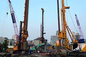
Various materials, for piping and back-fill around the pipe loops, have been tried with only marginal difference. Consequently the most common method is 32 mm piping of mdpe or hdpe material in a closed loop. Back-filling to avoid disturbing underground status is normally with bentonite or, where geotechnically possible, with fine sand. Typically the closed loop is inserted into a 150 mm borehole drilled to a depth of 50-100 m. Alternatively, if enough area of land is available, then a coil of the piping can be buried in a trench to a minimum depth of 1 m. Land limitations usually restrict use of this method to small systems.
Earth coupling is a simple robust technology that enables refrigeration and heat pump operation at high coefficient of performances (cop). It is energy-efficient, cheap to run, reliable, and has few moving parts. Importantly it is also maintenance free and requires no planning permissions. However, a lot of pipe surface area is necessary and boring or digging into the earth is expensive. This means costs for earth coupling are greater than for air coupling, at least for the UK climate, where typically a single borehole loop will exchange some 5-10 kW heat at conventional refrigeration temperature conditions.
It is essential that maximum use be made of an earth-coupled system. In the UK that means using it for heating. A heat pump will operate at a higher annual cop than an air source system, with cooling then coming as a free bonus facility to the owner in summer.
This elegant engineering is possibly the best application for earth coupling in the UK, since this country's air conditioning installations typically have to provide daily warmth in the morning, switching over to cooling, sometime between 11:00 h and 15:00 h, for the majority of the year.
Earth close to the pipe loop gives a natural diurnal thermal storage to the system, so that cooling of the earth enhances the take-up of heat from the refrigeration cooling, and so heat is then ready for draw-off the next morning. In this way an air conditioning system can be provided at an reasonable cost and be operated at high annual efficiency, producing low emissions.
Furthermore, with heating needs for buildings greatly reduced by better thermal performance and ventilation heat recovery, the heat pump sized for warming a building will not provide all its cooling needs. Under these circumstances the heat pump would be run to meet heating needs, separate air-coupled cooling plant would meet the normal cooling duty and the heat pump would cover the peak cooling duty.
Additional use of the diurnal thermal storage capability of an earth-coupled system can be also be obtained by the addition of an air-cooled or evaporative air-cooling facility onto the system. In certain circumstances air coupling will provide better cooling duty. Beyond that, the facility can then be employed during the cooler night-time to reject heat and re-cool the earth after it has been used to absorb heat during the warmer daytime.
For everyone's sake
It is evident that many opportunities exist to bring about significant improvements to refrigeration and heat rejection for air conditioning. And it is crucially important to the future well being of mankind that we exploit them all.
There is urgent need for a standardised assessment procedure to be agreed and for the various components of a system to have carbon performance ratings. This is so the emissions performance of overall systems can be dynamically modelled and assessed. It means the customer knows what is on offer and how well that fits with their overall strategy towards a carbon-neutral performance for their business activities.
A carbon-neutral strategy requires a 60% cut on present carbon emissions, and a reduction of 25% must be the minimum target for refrigeration systems. Remaining cuts can then come from switching to renewable or clean fossil fuels.
Source
Building Sustainable Design
Postscript
Terry Wyatt is head of research and development at Hoare Lea, and vice president of CIBSE. This article is part of a paper presented at the Institute of Refrigeration annual conference. For more information on the Institute and the conference, visit the website at www.ior.org.uk.


No comments yet