A bin analysis of annual outdoor dry bulb temperature allows the potential of fresh-air free-cooling to be investigated. The accumulated frequency curve for the number of hours of outdoor air temperatures for normal working hours (0700 to 1800) during a whole year, based on the average of the five year period 1976 to 1980 is shown in figure 1.
From this it is possible to determine the proportion of the total hours that were at and below a certain threshold temperature. To take account of heat pick up from the air distribution fan (assumed to result in a 1°C rise in the air stream) it is appropriate to take 12°C for a conventional mixing ventilation system and 18°C for a displacement system. The curve shows that fresh-air free-cooling can be used for 85% of the time for a displacement system but only 53% of the time for a conventional mixing ventilation system.
Although free-cooling reduces the energy consumed by refrigeration plant it is a potentially misleading term as energy will still be needed for fan, and in some cases pump, operation.
Potential energy
There are two ways to increase cooling capacity from a displacement ventilation system. First the supply air temperature can be reduced below the normal 19°C, though this not a viable option when the aim is to maximise free-cooling. It could also create unacceptable thermal comfort in the ankle region. Second is to raise the volumetric air supply rate. This allows a 19°C supply air temperature to be maintained, but increases the risk of high air speed in the occupied space. Fan power and duct sizing will also be increased.
BRE tests of a range of conventional displacement ventilation diffusers including floor swirl and bin type diffusers has shown that for an air supply temperature of 19°C, the maximum cooling load was around 20-25 W/m2. For higher loads the amount of air that must be supplied by the diffusers caused unacceptably high air speeds in the occupied space. Alternatively a larger number of diffusers would be required in the space which would significantly reduce space utilisation flexibility.
Earlier work elsewhere1,2 has shown considerable promise in the use of fabric diffusers in offices and restaurants to provide higher air flow rates without causing thermal discomfort from draughts.
BRE has tested a range of conventional wall diffusers and fabric diffusers, including fabric socks and bins, in a mocked-up office environment in BRE's environmental test facility. A conventional wall diffuser is shown in figure 2 (1·2 m high by 0·75 m wide) under test with an air supply of 19°C at 130 litre/s and a thermal load of 24 W/m2. The diffuser was also tested in a smaller test room with a thermal load of 54 W/m2. More than one diffuser would have been required in the larger mock-up to meet a load as high as 54 W/m2. This would take up valuable floor and wall space which would reduce space utilisation flexibility in an occupied building.
BS EN ISO 77303 relates the maximum acceptable air velocity to the air temperature and turbulence intensity as well as the occupants' activity and clothing levels. Taking into account these factors, and assuming typical office activity and clothing, the maximum recommended air velocity is between 0·15 litre/s and 0·2 litre/s and the maximum ankle to head height temperature gradient is 3°C.
Test results
The tests of the wall diffuser showed that with a thermal load around 50 W/m2 and an air supply rate of 130 litre/s thermal comfort within the diffuser outflow zone falls outside the normal limits of air speed and vertical temperature gradient for normal office work. However, outside the outflow zone thermal comfort is well within the limits. This reduces the usable floor area unless the diffuser outflow zone can be arranged to be used for general circulation areas or areas occupied for short times.
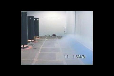
The fabric sock used in these tests was 4·25 m long and had a quadrant cross section so that it would fit into the skirting board position at the bottom of a long wall, figure 3. The aim was to provide a large surface area to allow high supply air volumetric flow rates without causing excessively high discharge air speeds or noise, and without taking up too much floor space.
Air was supplied into the sock through an opening at one end from an underfloor duct. The fabric created sufficient internal pressure for the discharge air flow to be relatively constant along the length of the sock as shown.
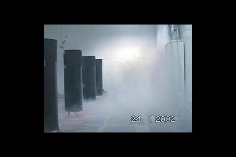
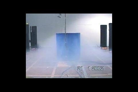
A prototype fabric bin diffuser included in the tests is shown in figure 4. This was constructed from the same material as the fabric sock and had diameter of 700 mm and height of 740 mm to give it a similar active area as the fabric sock. The bin was located in the centre of the room and was fed with supply air from a flexible duct run through the underfloor void. The resulting air flow discharge from the diffuser, shown in figure 4, was similar to the fabric sock, with little mixing with room air.
The fabric sock and bin were both tested at two air flow rates, 130 litre/s and 260 litre/s and 19°C air temperature. At the higher air flow rate the test room heat load was 2000 W which was equivalent to 48 W/m2. Air speed and air temperature were measured throughout the room space using a multi-channel anenometry system. Figure 5 shows the vertical variation of air temperature at various points along a traverse across the width of the test room (5·5 m wide) for the fabric bin.
The middle of the traverse was approximately 1·5 m from the diffuser. The measured temperature gradient between ankle and head height (0·1 m to 1·1 m for a seated person) at a point 1·5 m from the diffuser was 3·2°C. This is just on the limit of what is recommended as being acceptable by BS EN ISO 7730 for normal office activity and clothing levels. However, elsewhere the temperature gradient was around 2°C which is well within the comfort limit.
Figure 6 shows the vertical variation of air speed which is well within the 0·15-0·2 m/s limit. This is largely due to the low entrainment characteristic of fabric diffusers which causes little mixing between supply and room air. Overall the fabric bin diffuser provided acceptable thermal comfort apart from a zone within 1·5 m of the diffuser.
Comparison of the test results for the diffusers showed that overall the fabric bin diffuser provided a higher level of thermal comfort in the test room than provided by the fabric sock diffuser. This was largely due to the greater vertical temperature gradient close to the middle of the sock diffuser. The diffuser outflow zone is high at the middle of the sock diffuser as it is essentially a single sided diffuser whereas the bin has an unrestricted radial discharge. This is shown in figure 7.
The regions of high temperature gradient close to the fabric diffusers are a direct result of the low air entrainment in this region.
This would cause an unacceptably high ankle to head temperature difference for sedentary office workers seated close to the diffusers, but should not be a problem if these areas were used for general circulation or for areas which people occupy for short times, such as for drinks dispensers or photocopiers.
The size of the outflow zones would be smaller with lower cooling loads. The cooling load assumed in the tests was 48 W/m2 which is deliberately on the high side of the cooling loads found in typical office buildings to test the applicability of these diffusers to a wide range of occupancy levels.
The diffusers tested in this project would take up valuable office floor space. However, preliminary work has also shown that conventional floor tiles may be modified with fabric inserts to give similar performance as the fabric sock and bin diffusers. Whichever diffuser configuration is used, this work has shown the possibility of using appropriate wall diffusers and fabric diffusers with displacement ventilation to increase the cooling performance of these systems and opens up the opportunities for maximising the use of free ambient-air cooling in offices.
Acknowledgments
Some of the work described in the paper has been supported by the DTI's Partners in Innovation research programme and industry sponsors, including, Arup Research & Development, CIBSE, Dean & Wood Ltd, Gilberts (Blackpool) Ltd, Halton Products Ltd, Hoare Lea, Oscar Faber, Troup Bywaters & Anders, Trox (UK) Ltd and Waterloo Air Management PLC.
References
1Geens A J, Graham M S and Alamadari F. Displacement ventilation applications – an alternative view. 1997 CIBSE National Conference.
2Cullen N. High performance displacement ventilation using fabric diffusers – a case study. 2000 ASHRAE CIBSE joint conference, Dublin, 2000.
3BS EN ISO 7730: 1995 Moderate thermal environments – Determination of the pmv and ppd indices and specification of the conditions for thermal comfort. British Standards Institute, London, 1995.
Downloads
Figure 1: S-curve for occurrence of outdoor dry bulb temperatures.
Other, Size 0 kbFigure 5: Fabric bin diffuser – air temperature at 260 litre/s (48 W/m2)
Other, Size 0 kbFigure 6: Fabric bin diffuser – air speed at 260 litre/s (48 W/m2)
Other, Size 0 kbFigure 7: Outflow size from fabric sock and bin diffusers.
Other, Size 0 kb
Source
Building Sustainable Design
Postscript
David Butler and Michael Swainson are members of BRE's Environmental Engineering Centre.







No comments yet