


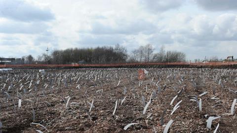
The contractor used 55,000 strips of permeable polyseter to enable work on a saturated site to start in months rather than years
Spanish paper manufacturer SAICA was looking to build a mill for recycling paper to make corrugated boxes on a site in Partington, adjacent to the Manchester Ship Canal. However the site it selected for its £290m investment had previously been a former petroleum storage depot that was now covered in layers of silt dredged from the bed of the canal.
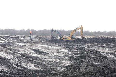
The silt had been spread haphazardly over the site at depths of up to 12m. As a result the ground was soft, compressible, saturated and, in its current state, incapable of supporting the new mill and its infrastructure. This was a serious problem for enabling works contractor Cheetham Hill Construction (CHC), which was tendering for the scheme.
It would have taken many years before the ground had settled naturally to a point where the site could be developed. One solution CHC could have adopted would have been to pile the entire site to carry the loads imposed by the mill, its car parks, access roads and stores, but piling on this scale would have been prohibitively expensive.
The site is covered to a depth of up to 12m of silt dredged from the Manchester Ship Canal
Surcharging the site, by adding a layer of spoil to the surface to help induce settlement, would have taken at least three years to have made an impact because the ground water held within silt’s pores lacked an easy path to escape from the ground.
The solution came through CHC’s early involvement of Balfour Beatty Ground Engineering (BBGE). The specialist geotechnical subcontractor proposed adapting a solution more commonly used in the construction of road embankments to help consolidate the soft silts. The solution involved installing a network of prefabricated vertical band drains – over 55,000 of them - to help induce settlement in the silt. If it worked, the band drains would enable construction of the mill to start in a period of months, rather than years.
CHC subsequently won the tender for the scheme based on Balfour Beatty Ground Engineering’s proposal. “If we had got our calculations wrong in the application of this solution to this site it would be an expensive mistake,” says Claire Garrett, Business Development Manager at BBGE.
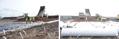
The temporary surcharge of spoil is added to help squeeze out the groundwater retained by the silt
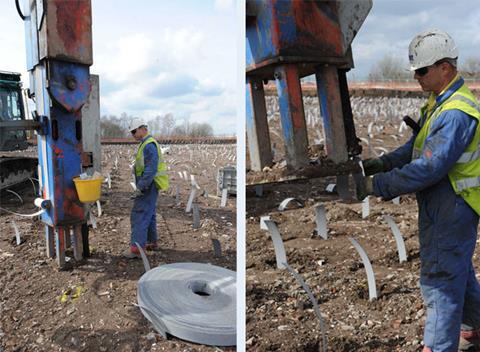
Balfour Beatty Ground Engineering started installing the band drains on site in January 2010. A band drain consists of a strip of permeable polyester 4mm thick, 100mm wide, which is wrapped in a filter membrane to keep it free of sediment.
This plastic strip is pushed into the ground to the base of the silt layer using a special crawler-mounted rig. Once in position the polyester strip acts like a wick by providing a pathway for the pore water from the silt to rise up through the drain’s polyester core to the surface where it can drain away more quickly.
Depending on the condition of a particular area of ground, the drains were installed on a triangular grid between 0.9 and 1.1m apart and between 8m to 12m deep.
To speed the silt’s settlement, additional weight was temporarily added to the surface of the site - a process known as surcharging. On this project, before the band drain was installed and the temporary surcharge added, the ground was covered with a geo-textile membrane. A 600 mm deep drainage blanket of granular material was spread over the membrane, which also served the dual purpose of helping support the weight of the band-drain rig.
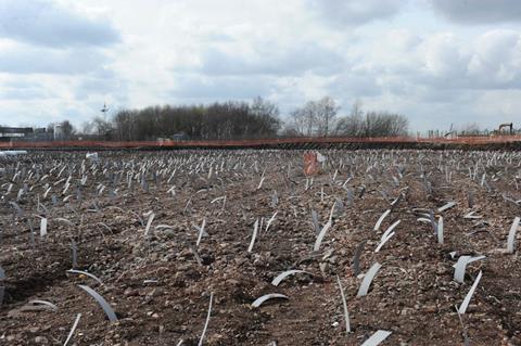
The band drains prior to the installation of the surcharge material
The band drains were then pushed down through the drainage layer and into the silt; they were terminated with 300 mm of the drain protruding above the granular blanket (see box How the drains are installed). A second geo-textile membrane was then placed on the granular layer. Finally the temporary surcharge is spread on top of the membrane at heights of between 1.5m to 3.5m, depending on the thickness of the silt below and its predicted settlement.
The additional weight of the surcharge increases the pore water pressure and helps to drive moisture from the silt to the band drain. Once the ground water has risen up the band drain, it discharges into the granular layer, where it becomes trapped between the two geo-textile membranes. A drainage system built into the granular layer then carried the water to a sump, where it was pumped from the site.The temporary surcharge is added to help squeeze out the groundwater retained by the silt
The key to making this solution cost effective was BBGE’s calculation of the induced settlements, the reduction in levels due to the site settling and the height of surcharge material. The greater the height of surcharge material, the quicker settlement would occur. The ground engineering specialist worked with CHC to find the most economical depth of surcharge to minimise the amount of material moved around site; this was balanced against the need to minimise the consolidation period so that construction could commence. Balfour Beatty Ground Engineering calculated that a depth of between 1.5m to 3.5 m of surcharge, depending on the thickness of silt layer beneath, was the most cost effective solution, which would produce the necessary settlement over the shortest time period.
The band drains are installed by a specially adapted crawler rig Balfour Beatty
CHC wanted the bulk of the settlement to have occurred prior to any construction work taking place. With up to 3.5m depth of temporary and permanent surcharge material and the band drains spaced on average 1m apart, Balfour Beatty Ground Engineering predicted that settlement would be accelerated to the point where enough ground water will have been squeezed from the dredged silt over a 3 month period to ensure 85 % of voids will have disappeared.
The predicted drop in ground level was a critical factor in calculating the amount of up-fill material and surcharge material needed. “The contractor relied heavily on our predictions to ensure they had enough material to make up the ground back to the same level,” explains Garrett. Cleverly, the depth of up-fill material needed to restore the ground to its original level was placed on the ground before it had settled. By adding the permanent up-fill prior to the settlement occurring, Balfour Beatty Ground Engineering minimised the height of temporary surcharge material required to induce settlement as the permanent up-fill was acting as surcharge in itself, minimising the amount of earth that had to be moved.
In all, 65 000 m2 of the 155.000m2 site was treated to consolidate the ground and ensure that it had sufficient load bearing capacity to support the installation of the paper mill’s infrastructure. The only exception was the area of ground beneath the mill itself; this has remained untreated because it will have to be piled to enable it to support the enormous loads imposed on it by the new mill.
Once all the band drains were installed and the surcharge in place Balfour Beatty Ground Engineering continuously monitored the ground levels. Remarkably, the ground level had dropped by its predicated amount of between 200 to 600mm, depending on the depth of silt beneath. “The treatment produced better than expected results,” says Garrett.
The silt is expected to settle a further 75mm over time. However, the scheme has been designed to accommodate this long term settlement. In April, after the specified three month consolidation period the surcharge could start to be removed to allow the remainder of the enabling works to progress bang on programme. With the silt now drained, construction is underway and the mill is expected to open February 2012.
How the band drains were installed
The wicking material for the band drains was delivered to site in 280m long rolls. The rolls are mounted on a specially adapted crawler rig for installation. To install the drains a length of wicking material is threaded through a hollow mandrel and attached to a lance. A slotted anchor plate is then attached to the foot of the wicking material before a Rig-mounted stitcher mast pushes the lance through the up-fill and into the silt, to depths of up to 12 m. It was important to control the depth of the lance because the silt had been deposited on top of a layer of relatively impermeable glacial clay; this was overlaying a sandstone aquifer. “We had to be careful we did not penetrate the aquifer,” explains Matthew Truelove, contract engineer for Balfour Beatty Ground Engineering. Once the lance reaches the required depth, the mandrel is extracted leaving the drain anchored in place. The wicking material is then cut to leave about 300 mm protruding from the ground. This procedure was repeated over 55000 times using up to 5 rigs each installing up to 600 band drains a day.


1 Readers' comment