On a tight site whose logistical challenges include four London Underground tunnels – not to mention an immoveable deadline imposed by the presence of the ticket hall for Waterloo tube station – the £1.5bn Southbank Place is rapidly taking shape, using BIM and prefabrication to push the project along.
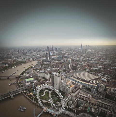
This project is one of the most technically challenging and programme driven we have ever done,” says Simon Bourne, project executive at Canary Wharf Contractors (CWC). In one sentence Bourne has summed up the construction of Southbank Place – one of the largest and most complex construction projects under way in London.
Situated, unsurprisingly, on the south bank of the River Thames, this tricky site is located above four London Underground tunnels; it incorporates the western entrance and ticket hall for Waterloo underground station. A railway viaduct bounds it to the north, while to the east is the busy York Road and to the south the Chicheley Street public access to Jubilee Gardens and the London Eye.
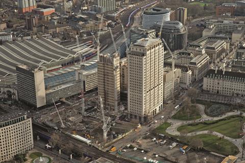
Previously the site was the UK home of oil company Shell in the form of a 27-storey office tower and an adjoining nine-storey horseshoe-shaped block. The low-rise block has been demolished as part of this project (see panel) but the 27-storey Shell Tower remains; it will continue to be occupied by Shell throughout the site’s redevelopment, adding one more logistical challenge for the constructor.
It is on this constrained 20,000m2 plot that CWC is racing to build two new office blocks and six residential towers along with retail and restaurant units for joint venture developers Canary Wharf Group and Qatari Diar. To meet the £1.5bn development’s demanding programme, CWC is embracing both innovative structural solutions and advanced construction techniques combined with detailed project planning using 4D BIM.
One of the most technically challenging buildings on the site is Building 3 – or Four Casson Square, as it is known by the marketing team. This 29-storey residential tower, designed by architecture practice Patel Taylor, is situated adjacent to York Road. It is scheduled for occupation in autumn 2019.
It is in this building that the ground floor is also home to the western ticket hall and escalator access to Waterloo underground station. The station access is currently closed but is scheduled to be handed back to London Underground by summer 2018, over a year before the tower’s slated completion. “The deadline means all of the building’s cladding has to be installed before the ticket hall can open,” explains Bourne.
Prefab approach
To drive forward the tower’s construction CWC is working with its structural engineer WSP and concrete contractor Expanded Civil Engineering (part of Laing O’Rourke) to prefabricate most of the tower’s above-ground structure.
Below ground, the tower’s two basement levels and the ground floor slab are cast in situ in concrete. This subterranean structure supports three giant, 30m long and 2.4m high steel transfer beams, which span the ground-floor ticket hall concourse. Steel beams were used in preference to forming the beams in concrete, because it shaved two precious weeks from the construction programme. It is above this transfer structure, where the structural grid is more regular, that Expanded is driving upwards using Laing O’Rourke’s Design for Manufacture and Assembly (DfMA) precast concrete solution. “We chose this construction method on the basis of driving down the programme, reducing deliveries and labour on this already congested site,” explains Bourne.
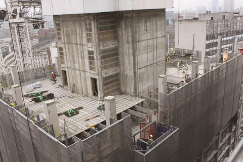
On site Expanded’s concreting team is working its way up the building towards the top of the completed 29-storey core. It has just poured the floor slab at level 21 and is beginning level 22, placing steel reinforcement on the floor’s concrete deck in advance of the next pour. On first impressions this would appear to be a fairly conventional construction solution. However, the floor’s deck is assembled from pre-cast concrete planks that form the underside of the soffit.
Each plank incorporates reinforcement specific to its location on the floor slab. “The clever thing about this is that it is not simply pre`cast concrete formwork, but all of the bottom-mat reinforcement is already cast into the slab,” says Bourne. Once the top-mat reinforcement and temporary perimeter shuttering have been fitted, the upper half of the floor slab will be poured to knit the floor structure together.
The 200mm-thick floor will then be post-tensioned, once the concrete has gained sufficient strength. The precast concrete floors are supported on precast concrete columns; these terminate just above slab level to allow the columns that support the floor above to be installed without having to wait for the wet concrete slab-topping to cure. Table formwork is used to support the precast soffits and precast columns ready for the rebar installation team to commence work. It is a simple, clever solution to speed up construction; each floor slab is done in two halves, which keeps the concreting team separate from the precast installation team.
All the steel reinforcement within the precast elements has been modelled in 3D, as part of the project’s detailed BIM model. The benefit of such detailed modelling is that at the point the precast slabs abut the precast columns, the reinforcing bars protruding from the column thread precisely through the shear rails cast into the precast concrete slabs. “It is a structural masterclass,” says Bourne.
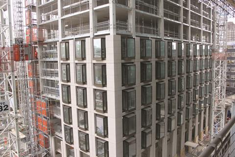
In addition to being supported on a precast concrete structure, Building 3 is also clad in precast concrete. Cladding installation has reached level seven. The storey-height precast panels are W-shaped, with a glazed window in each U of the W. To speed up installation and reduce the number of operatives needed on site, the curtain walling contractor McMullen Facades has pre-installed the glazing into the panels at Laing O’Rourke’s Worksop manufacturing centre.
These cladding panels are also unusual in that they are post-tensioned. Post-tensioning the panel’s base ensures that the W-shaped panels are stiff enough to be lifted into position by crane. There is also, in addition, a temporary steel beam that is bolted across the top of the W to prevent damage during transit and lifting, which is removed once the panel is in place.
Post-tensioning allows the cladding panels used on the building to be thinner and lighter. It also helps prevent hairline cracks appearing in the surface of the concrete, which could show as blemishes over time. Bourne says this is the first time this type of post-tensioned cladding solution has been used. “This system gave us the programme assurance needed to meet the ticket hall handover deadline,” he explains.
CWC’s choice of cladding contractor to speed construction could have backfired badly, when McMullen Facades went into administration last year. However, following its takeover by concrete specialist JRL that same month, November, any crisis appears to have been averted. “It is business as usual, with the same team working on the project,” says Bourne.
BIM in the basement
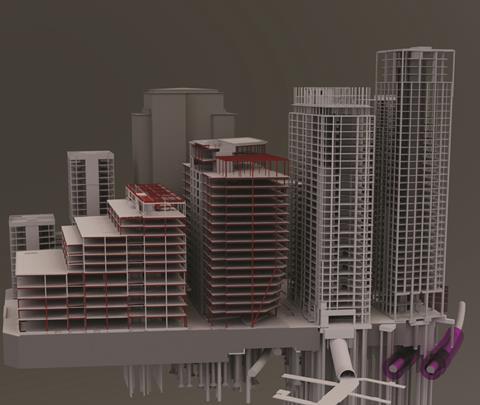
BIM has been used on this project from the outset, where it was used to sequence demolition of the nine-storey block and its 200m x 100m x 12m deep basement to enable construction to get under way at the earliest opportunity.
Demolition of the low-rise block had to be undertaken carefully. CWC started on site in August 2015 with asbestos removal and then the subsequent demolition of the low-level block and the structures contained within the site-wide basement. “We had to prevent the sudden unloading on the ground, which might have caused the underground tunnels to rise upwards,” says WSP’s Audrey McIver. “There was some kentledge used until we built the transfer structures to put the load back on top of the tunnel,” she adds.
Unusually for London, the Shell building’s 1960s-built basement retaining wall is formed of post-tensioned concrete. “We took advantage of the post-tensioning to demolish everything inside the basement, including a swimming pool, rifle range and theatre. The post-tensioning allowed CWC to work in the basement tub without the need for props to support the wall, which helped free up space on site,” says McIver. She adds: “We did consider reusing using the existing basement slab, but because we had to punch through it in places for lift pits and piles we built a new basement raft on top of the existing [one] to distribute loads over the slab.”
Ticket hall and station
As construction of Building 3 races upwards, down on its ground floor the drive to construct the ticket hall and underground station access is pushing ahead. Here Bourne points out another innovation, what he calls the “clever soffit”.
The ticket hall’s precast concrete soffit was installed soon after the transfer beams had been craned into position to enable installation of the underground station’s three new escalators to get under way. The soffit is directly below the giant transfer beams. Its installation early in the tower’s construction means that as construction races upwards, loading on the transfer beams will increase and the beams will deflect. The precast concrete panels forming the soffit have been designed with a support in each corner and a compressible layer of material sandwiched between the panel and the structural soffit above, to enable these deflections to be easily accommodated.
Residential towers
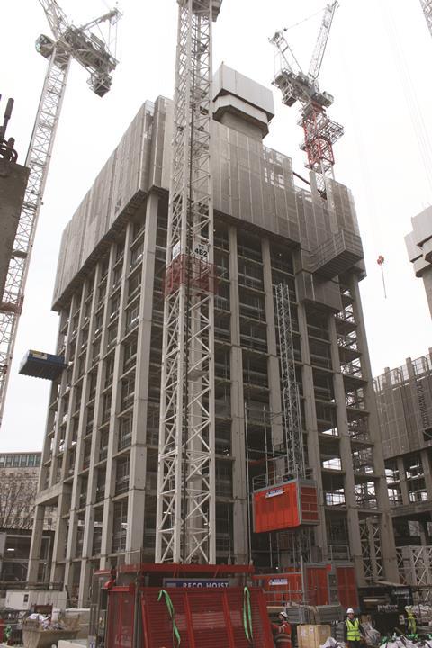
To the north of Building 3, adjacent to the railway viaduct, construction of the concrete slip-form cores for Buildings B4A and B4B (aka One Casson Square and Thirty Casson Square) are racing skywards. The core on B4A has reached level 16, while the floor slabs are up to level 10, while on B4B the core is at level 20, with the floor slabs at level 14.
Designed by architect Squire and Partners, these two residential towers will top out at 37 floors and 30 floors respectively. Sequencing means that construction of these two blocks is less advanced than for Building 3, giving onlookers a clear view of the climbing screens being used to construct the floorplates – the DfMA system is not being used for these two towers. “For safety reasons we insisted on a fully encapsulated screening system because the site is so congested and, in this case, within a handshake of the railway,” says Bourne. The screens extend downwards for four floors to allow the formwork supporting construction of the lower floors to be dismantled and returned to the work face using an in-built formwork lift. “You never, ever, have any work happening outside of the screen,” explains Bourne.
B4A and B4B also happen to be the tallest residential towers on the scheme. B4A is being built directly above the two London Underground Northern line tunnels on piles threaded either side of and between the live tunnels. In places the piles come to within a metre of the ancient tunnels. “Above ground you cannot appreciate the complexity of the challenge that had to be resolved below ground,” says Audrey McIver, technical director at CWC’s structural engineer WSP.
An additional challenge that comes from building high-spec residential blocks so close to the tube lines is the problem of transmitted noise. The development’s residential buildings above the tube lines, and the commercial building B2, incorporate acoustic elastomeric pads that isolate the basement structure from the superstructure to help minimise structure-borne noise. Detaching the superstructure from the basement structure means that the towers’ cores become unstable above 50m. “When the buildings have been completed, they are so heavy that they are stable, even when the wind blows, but under construction, those buildings need additional support,” explains McIver.
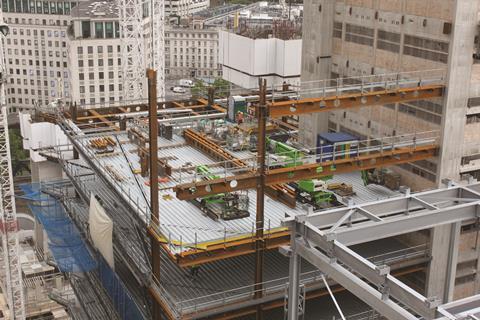
The solution developed by CWC’s temporary works engineers is to clamp the superstructure to the basement structure using a series of giant Macalloy bars attached to corbels cast into the core above and below the acoustic pads. Using Macalloy bars allows CWC to clamp the top of the tower to its base. Each bar has a load cell attached. As the building rises upwards, the increased loading will cause tension in the Macalloy bars to gradually disappear; based on the output from the load cells, CWC’s engineers are able to see when to re-tension the bars.
To the south of Building 3, the structures of the first two residential towers, Buildings 6 and 7 (aka Belvedere Gardens), are now complete and this part of the site is clear of tower cranes. “The DfMA solution meant there were fewer people needed on site and construction finished well ahead of programme; it’s the way forward,” says Bourne. Fit-out of the apartments, which are 70% sold, is under way ready for summer 2018 handover.
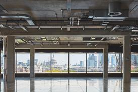
The structures of the two commercial office blocks, B1 and B2 (One Southbank Place and Two Southbank Place), have also been completed. The offices’ large 17m floor spans mean that steel beams rather than concrete are used to support the floors of these buildings. Both blocks do, however, incorporate a large concrete core. “Cranes have been the key to completion of the commercial buildings: we slip-form the building’s core to the top and then place the cranes on top; once the ground-floor slab is complete we hand over the building and its cranes to the steelwork teams so that they can work without interruption,” explains Bourne.
The pace is as relentless as the project programme, with about 1,500 operatives now on site, to ensure that One Southbank Place and Belvedere Gardens along with the Waterloo ticket hall are ready for their summer 2018 handover.
Project Team
Client: Canary Wharf Group/Qatari Diar
Main contractor: Canary Wharf Contractors
Architect: Patel Taylor / Squire and Partners / Kohn Pedersen Fox Associates / Axis Architects / Grid Architects / Adamson Associates International / Stanton Williams / Goddard Littlefair /Townshend Landscape Architect
Structural engineer: WSP
Concrete contractor: Expanded Civil Engineering
Cladding: McMullen Facades/JRL







No comments yet