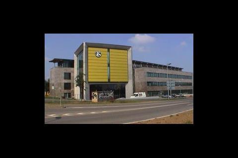
The building comprises a volume of approximately 25 000 m3, including approximately 3500 m3 for the subterranean garage, and floor space of approximately 2500 m2. It offers space for individual offices with a total of 155 workplaces and conference rooms for around 90 participants. The building comprises two office wings, clad in natural stone, arranged at an angle of 7°C to one another. Service risers, communal and sanitary areas are located between these two wings.
The windows have sun protection glazing with electrically operated internal blinds which close from bottom to top automatically according to the intensity of the sunlight and can also be activated manually. This provides for indirect natural lighting over the white painted concrete ceiling.
The windows are openable, but this feature is used extremely rarely due to the location along the approach to the Stuttgart airport. A mechanical ventilation system provides for controlled air supply at the minimum hygienic air exchange rate. The architectural requirements for a smooth visible concrete ceiling offered the possibility of activating this structural element to dissipate the expected cooling load.
The system of concrete core cooling utilising ventilation air developed by the Kiefer company of Stuttgart matched the overall system concept. In close cooperation with the Kiefer company, consultants Laux, Kaiser & Partner, and the architect's Arat, Siegel & Partner developed an optimum solution for the building owners and users.
System description
Concrete core cooling with incoming ventilation air makes use of the high storage capacity of the concrete ceiling. The ventilation air flows through aluminum cooling tubes – for good thermal conductivity – which are laid in the concrete ceiling. To improve the heat transfer from the tube to the air, the inner surface has been ribbed, tripling the active area. The high exchange rate between the air and concrete ceiling allows the ceiling to serve as a decentral reheater for the incoming air while simultaneously cooling the ceiling. This reheater operates without any primary energy using the cooling load from the room.
The required quantity of outdoor air flows in through the finned tube at a temperature of 12-14°C and then exits through suitable outlets into the room, achieving a heat transmission rate of up to 90%. This means that the incoming air leaves the tubing at a source air temperature of 21°C after flowing through the concrete ceiling with a temperature of 22°C and active finned tube length of 7-10 m.
Due to the low initial temperature of the incoming air before entering the finned tube, considerable energy savings can be expected over the service life of the building. Over approximately 6000 hours/year (VDI 4710, Stuttgart), is available to the outdoor air with a temperature of 12°C. Considered only for the winter, this is a saving of approximately 19 kWh/m²year in terms of the air heating based on the operating time.
The regenerative heat reclamation preheats the outdoor air to 10°C with the fan heating it again by 1-2°C depending on the pressure increase. The air can then flow through the duct network into the cooling tube without further thermal treatment.
For summer use, there are various opinions regarding the degree of cooling and dehumidification. Research by Fanger and Steimle, states that dehumidification of the ventilation air contributes significantly to comfort and working ability of the occupants. This means that during the summer months, cooling should also be provided at a value of 12°C combined with dehumidification to achieve a satisfactory and productive room climate.
The energy consumption for cooling/dehumidification then amounts to approximately 22-25 kWh/m2a at an airflow rate of 7·5-10 m3/hm2 (2·08-2·77 l/sm2). With systems using water to cool the concrete ceiling, the additional energy consumption required to cool the water must be added. This amounts to 80 kWh/m2year and 100 kWh/m²year at cooling capacities of 40 W/m² to 50 W/m² and an operating period of 2000 h/year. The concrete core cooling system with incoming air therefore reduces the cooling capacity required to approximately 20% while maintaining the same or even greater comfort.
The greater comfort results from around 1-2°C lower room air temperatures, as the ceiling is cooled actively during occupation of the room.
Night cooling, if required, is accomplished at a reduced flow rate using a variable speed motor. The air quantity can also be adjusted to the reduced flow rate during the day following the initial phase (after purging has been completed). This provides an additional contribution to the energy savings.
System engineering
The central air conditioning system is equipped with a regenerative heat reclaim function. At low outdoor temperatures, the heat reclaim function heats up the outdoor air to a temperature at which it can enter the cooling tube. The cooler/heater located behind the fan is intended to ensure the required incoming air temperature in the event of failure of the heat reclaim system.
Other zone coolers and reheaters serve the individual building zones to provide appropriate incoming air temperatures. Level three was equipped with a water-cooled intermediate ceiling due to the planned wooden ceiling and also provided with source air as ventilation. For this reason, the incoming air for level three is reheated to the displacement air temperature after exiting the ventilation unit. The incoming supply air then flows through the distribution duct network and appropriately arranged fire protection dampers into the individual storeys.
Due to the pressure loss in the cooling tube and corresponding layout of the incoming air duct, volume control is accomplished without additional flow rate regulation. The pressure loss in the cooling tubes acts as a compensating final resistance. Flexible hoses are used to connect the incoming air duct to the individual cooling tubes. An area for installation of the source air inlet is located on the inside of the office partition wall and the source air enters the room through a louvre grille located in front.
Due to the temperature/density difference, the incoming air flows downwards from the ceiling and then to the heat sources causing it to rise again. The exhaust air is drawn through a gap in the ceiling into the recess and then into the airtight plenum in the ceiling through a transfer duct. The inner lining of the transfer duct allows it to act as a crosstalk silencer. The exhaust air then flows into the exhaust duct through projection nozzles (figure 1).
Operation
The system is switched off at the end of each working day, allowing the system to continue to run will not provide any energy advantage because during hot periods of the year the outdoor air temperature is still significant high during the evening hours. The natural night cooling of the outdoor air is used to retro cool the ceiling during the morning hours with cooler air and thereby lowers energy consumption.
With this cooling operation, the heat still present in the ceiling from the previous day is dissipated with a time offset. The start time is determined by a night check of the room/exhaust air temperature and depends on the average quantity of heat still present in the room. It is calculated using a number of parameters specific for the building.
Installation description
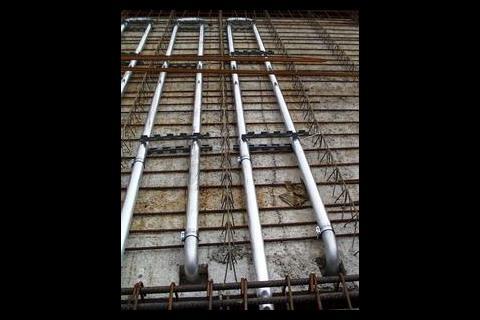
The building was constructed using in-situ concrete. The only exception was the ceilings above the offices, here 60 mm precast slabs with extended cagework were attached to the main cagework before the final pour – this helps to give a controlled surface and a better overall appearance. The cooling tubes were prefabricated and delivered to the construction site with the aid of transport racks.
It was necessary to complete one of the four pipe connections on the construction site, because the feed line from the corridor area led through the structural steel for the joist. Plastic spacers ensured a constant position of the tubes in the neutral zone of the ceiling slab. The upper structural steel, which had not been laid (see picture), was connected to the spacer blocks located on the cage work concrete slab in the longitudinal direction.
This connection prevented the cooling tubes from floating up while the cage work concrete slabs had prefabricated cutouts which were closed at the bottom with formwork. The tubing elbows were made watertight on this formwork as well as that laid in the hallway area with the aid of positioning plugs.
After laying, the upper structural steel, the concrete was poured permanently casting the tubing into the ceiling. After removal of the formwork, the positioning plugs remained in the elbows where they serve to protect the tubing against dirt entering. The plugs and any concrete which ran beneath was removed when the flexible hoses were connected.
Operating results
The system of concrete core cooling with incoming air had to pass a strenuous test at the very beginning. During the week of August 20-26 2001, outdoor temperatures of over 37°C were measured. The offices were already in full use and the interior as well as exterior loads had already reached their maximum value. The measuring sensors integrated into the control system for the individual building zones and outdoor values were logged and evaluated. Figure 2 shows the temperature values for this week, the room temperatures reached a maximum of 25·4°C. Due to the large surface cooling capacity and gentle air inlet no concern or dissatisfaction of the room air climate were noted.
The future
Another project already in operation is an office and administration building in the area of Frankfurt/Main. Here, the largest project with approximately 15 000 m² is also in the final construction phase. In the area of Hamburg, two further projects with floor space of approximately 2000 m2 each, are also in the completion phase. Practical experience with the Kirchhoff project clearly shows that the concrete core cooling system with incoming air fulfills and exceeds all expectations in terms of its integration into the construction sequence as well as in terms of overall performance.
Energy-optimised planning of modern office buildings should take this system into consideration at the very beginning of initial planning. Due to its high energy savings potential, it helps users as well as investors to equip buildings with engineering to achieve extremely favourable consumption values and meet high comfort demands.
Building data
Room volume, not including subterranean garage (gross): 21 500 m3Main floor space (gross): 2500 m2
Air conditioned office floor space
Based on concrete core cooling with incoming air system
Axis interval: 7·55 m
Number of modules per axis: 6
Module width: 1·2 m
Module depth: 5·24 m
Module area: 6·55 m²
Number of modules, total: 239
Total area: 1565 m3
Total air quantity
Offices, zone west 1: 5940 m3/h
Offices, zone west 2: 3960 m3/h
Offices, zone east: 5760 m3/h
Total: 15 660 m3/h
Specific air quantity:10 m3/hm2
Downloads
Source
Building Sustainable Design
Postscript
Clemens Kiefer Dipl Ingenieur is senior engineer with Kiefer GmbH.
Credits
Architect Arat Architect Siegel & Partners Consulting engineer Laux Consulting engineer Kaiser & Partners General contractor HochTief AG System construction and concrete core cooling with incoming air Kiefer GmbH. Luft - und Klimatechnik









No comments yet