


This CPD module, sponsored by Dow, will examine a range of factors which need to be considered when addressing ground floor insulation, including construction techniques
CPD CREDITS: 60 MINUTES
DEADLINE: 13 JULY 2018
For more information about Assemble Media Group’s CPD distance-learning programme, click here


INTRODUCTION
While it has long been common practice to insulate upper floors to reduce noise and to cut heat loss, only since 1990 have Building Regulations required that ground floors be insulated in order to save energy.
This CPD module will examine a range of factors which need to be considered when addressing ground floor insulation, including construction techniques, the impact of thermal bridging, calculating U-values and the impact of insulation on a project’s design.
Basic principles
Floors are classified as:
- ground floors, in contact directly or indirectly with the ground
- exposed floors, forming the lowest part of a structure over unenclosed airspace (for example a balcony)
- intermediate floors, having heated space above and below.
Ground floors may be ground-bearing or suspended. All other floors are, by definition, suspended.
The ground absorbs heat from floors close to or in contact with it, which is increased by high soil moisture content. When combined with the natural temperature gradient in buildings this can lead to an uncomfortable internal environment, condensation at wall or floor junctions and higher-than-predicted energy use. Exposed floors suffer heat loss to air, in the same way as other building elements.
Heat loss can be reduced by including in the floor construction a layer of thermal insulation continuous with that in the rest of the building envelope. This also helps avoid thermal bridges – where the integrity and continuity of the horizontal floor insulation is broken at the point where the floor meets external or load-bearing internal walls. It is important, however, that a floor’s functional requirements are not compromised by any thermal insulation.
Structures below ground must prevent ground water reaching the interior of a building in order to maintain suitable internal conditions (see BS 8102: 2009 for gradings). A common way of providing waterproofing is to use externally applied tanking membranes of mastic asphalt or bituminous sheet.
When externally insulating basement walls insulation boards are laid against the tanking membrane and the excavation is then backfilled. The construction is then suitable for new build and refurbishment projects.
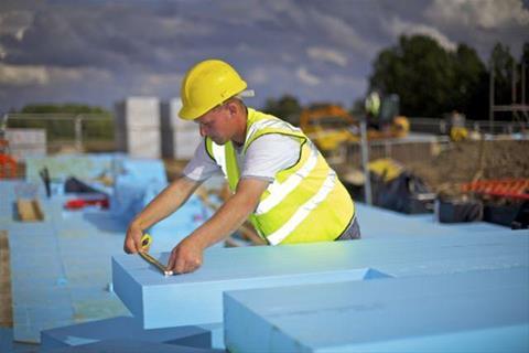
Floor construction
The construction of ground floors typically includes ground supported concrete slabs; suspended concrete floors (including beam and block systems), and suspended timber floors. The BRE’s Good Building Guide 28, Part 1, provides specific constructional details for these floors.
BRE highlights that a ground floor construction’s primary function is to prevent the transfer of moisture from the surrounding ground through it and into the interior of the building. Damp-proof membranes (dpm) should be continuous with any vertical and horizontal damp-proof courses (dpc).
Various thermal insulation materials are available to boost the thermal performance of a ground floor and should be appropriate to the specific application. It should have the required density, or compressive strength, and relevant water absorption characteristics.
Retrospective fitting of insulation in ground floors can be carried out, however this is likely only to be economically viable during major refurbishment of the floor. In order to minimise the potential thermal bridge – effectively a break in the integrity and continuity of the horizontal floor insulation at junctions between the floor and external walls or load-bearing internal walls – wall and floor insulation should meet or overlap, where practicable.
Insulating concrete ground floors above and below a structure require different approaches.
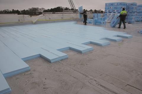
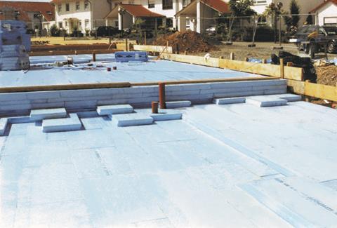
Concrete ground floors insulated below the structure
Insulation is laid horizontally over the whole area below the main structure of the floor and should typically be rigid boards featuring a high moisture resistance and compressive strength. BRE states that dpm may be placed either above or below the concrete slab, and if placed below the concrete can be above or below the insulation.
If the insulation is placed below the dpm it must be resistant to any contaminants with which it may come into contact from the ground or fill material. On landfill sites and on ground containing high levels of sulfates where the dpm is designed to be above the concrete an additional membrane may also be needed beneath the concrete to provide separation from ground contaminants.
Design and construction considerations
As ground-supported slabs are cast directly onto the insulation, deformation of this insulation layer could lead to initial subsidence, unexpected floor stresses in the floor slab and a reduction in thermal performance. Additional compression or degradation could result where insulants react chemically with contaminants in the ground or fill.
BRE suggests the following guidance avoids deformation of the insulation:
- Use insulation which has sufficient compressive strength to resist the weight when placing concrete, the completed slab, the anticipated floor loading in use and any possible overloading or point loading due to stored materials. With some floor slabs the insulation must have sufficient compressive strength to act as shuttering during concreting of the floor slab.
- Use insulation with low water absorption and a high resistance to chemical attack. In high-risk situations place the insulation on a dpm or separating membrane.
- Ensure that all hardcore and fill materials are well compacted and covered with sand blinding to provide an even and level support for the insulation.
Gaps in the insulation can occur as a result of poor fitting and disruption due to placing of the concrete. Placing the dpm above the insulation prevents concrete running into the joints between the insulation boards and ensures that sharp objects in the blinding or fill material do not puncture the dpm.
When tamping and power trowelling the concrete surface protect the edge of the dpm and insulation with a board. Consider using hand trowel finish close to the edge of the floor.
Thermal bridging
The integrity and continuity of the horizontal floor insulation will be broken at junctions between the floor and external walls or load-bearing internal walls. This break in continuity will result in a thermal bridge and a risk of localised surface condensation. To reduce this bridging risk along the external walls, cavity insulation should be extended below the dpc and below the base of the floor slab.
Where appropriate, lightweight concrete blockwork should be used in constructing the outer wall below dpc level. And where practicable, a vertical strip of insulation should be fitted around the perimeter of the floor slab, either overlapping with cavity insulation or linking with any internal wall insulation.
Internal load-bearing walls which penetrate the floor structure creating a thermal bridging risk should also have a vertical strip of insulation placed against the internal faces of the wall or lightweight concrete blockwork should be used below floor level.
Care should be exercised at the thresholds of external doors to lower the risk of thermal bridging where the external wall is bridged to accommodate access. This risk may be increased where a level threshold detail is necessary to allow an unobstructed surface between inside and out. A typical level threshold detail could be where the insulation is returned along the edge of the floor slab to reduce the risk of bridging.
Concrete ground floors insulated above the structure
Insulation above a concrete floor is generally associated with suspended pre-cast construction, such as concrete beam and block systems. Insulation can be installed above an in-situ concrete floor as long as the dpm is placed above the structural slab to reduce the risk of damage to moisture sensitive floorings. The insulation is normally placed below a timber-based flooring system or below a relatively thin sand cement screed. It should be rigid and suitable for the loading requirements of the floor.
Insulating above the structure is suitable where an existing concrete or timber suspended floor is to be replaced or overlaid by a new floor structure.
Design and construction considerations
Bumps or undulations on the concrete slab or precast flooring can lead to movement of the floor finish leading to unevenness and subsequent disruption of the floor finish. Where a timber-based flooring system is to provide the floor finish it may be necessary to lay a concrete levelling screed in order to provide a suitable level surface to receive the insulation and floor finish.
BRE states the insulation board should have adequate compressive strength for the intended purpose and where additional floor loading is anticipated – for example below kitchen and sanitary fittings, static equipment or door openings – timber support battens should be provided.
Where a cement sand screed finish is to be laid this should be a minimum 65mm thick. The screed should be thoroughly compacted throughout its thickness, particularly above resilient insulation. Joints of rigid insulation boards should be taped to ensure wet screed does not penetrate the joints. A separating layer such as building paper or polyethylene sheet should be positioned above fibrous insulation to prevent moisture from the wet screed being absorbed by the insulation.
Some plastic insulation products may be damaged by the solvents in some liquid dpm materials and adhesives. Ensure that insulation materials that may be at risk are not laid until the solvents have fully evaporated.
Damage to moisture-sensitive floor finishes
Moisture-sensitive floorings including timber-based flooring panels (particularly those of chipboard) can be seriously disrupted or damaged by water vapour arising from moisture within the floor construction. If there is no dpm above the concrete floor a vapour control layer, such as polyethylene, should be placed between the insulation and the screed to protect moisture-sensitive finishes. The screed should be allowed to dry before any floor finish is laid.
Thermal bridging
As with insulation placed below the structural floor there is a potential thermal bridge at the junction of the floor and the external wall and where the insulation is omitted around service penetrations. The continuity of the insulation can be achieved by linking with internal insulation or over lapping with cavity insulation. Additionally, the use of lightweight concrete blocks for the inner leaf below the floor slab reduces the risk of thermal bridging.
U-values and insulation products’ performance
The U-value or thermal transmittance of a building element or component is a measure of its ability to conduct heat from a warmer environment to a cooler environment. It is expressed as the quantity of heat (in watts) that will flow through one square metre of area divided by the difference in temperature (in degrees K) between the internal and external environment. The resulting unit is W/m²K.
For example, if a square metre of area allows one watt of heat to pass through it when the difference in temperature is 1°C, then the U-value of that element is equal to 1W/m²K.
However, the calculation of a U-value is often complicated by the presence of repeating thermal bridges, such as gaps and voids, which effectively allow some of the heat to bypass the insulation.
The rate of heat loss thorough a floor situated next to the ground varies with its size and shape. It is possible, if the floor is large enough, to achieve a target U-value of 0.35 W/m2 K without the use of any additional thermal insulation, but only for floors over 400 m2. For most housing, therefore, as for other small buildings, it will be necessary to add thermal insulation to meet this target value. For floors where the thermal insulation must be added, the thickness will depend upon the thermal conductivity value of the material, and the shape factor of the floor. The shape factor is a simple ratio of heated perimeter length divided by heated perimeter area, or P/A. most of the heat from a floor is lost around the perimeter, and on large floors with a low P/A ratio, only perimeter insulation may be necessary to achieve the required U-value.
Other aspects which will affect the U-value calculation are the ground conditions, e.g. clay, sand/silt and rock, as these have different thermal resistance. The wall thickness will affect the U-value calculation as well.
BRE says most wall and roof constructions, as well as most types of floor decks, may be assessed using the method for calculating U-values given in BS EN ISO 6946 and CIBSE Guide A3. These documents describe the ‘combined method’ for repeating thermal bridges and give correction procedures for the effects of metal fixings, air gaps, rainwater percolation and unconditioned buffer spaces.
A roof, wall or floor construction will often adjoin an unheated space rather than the outside environment. In such cases, the unheated spaces will act as a buffer, reducing heat loss and thereby reducing U-values.
With the development of energy calculation tools such as the Standard Assessment Procedure and the Simplified Building Energy Model (together with its user interface iSBEM), which support the national building regulations for conservation of fuel
and power, as well as the production of Energy Performance Certificates, U-values and thermal mass values need to be reliably calculated for a range of construction types.
The table (below) features three examples of insulation materials and the thickness needed to achieve a target U-value of 0.25 W/m2K for three different P/A ratios, in a ground-bearing floor:
| Thickness required (mm) | ||||
|---|---|---|---|---|
|
Insulation material |
λ (W/mK) |
P/A = 0.40 |
P/A = 0.60 |
P/A = 0.80 |
|
Polyurethane |
0.023 |
50 |
60 |
65 |
|
XPS |
0.033 |
70 |
85 |
95 |
|
EPS |
0.038 |
80 |
95 |
105 |
Floors and applied loadings
Another vital function of a floor is to support the loads placed on it during the life of the building. With some types of building, loadings are easy to predict and unlikely to increase with time. With others, particularly with industrial buildings, change of occupancy or developments in production may require floor strengths to be increased from those originally considered adequate.
Any material will compress when a load is placed on it. In this case, the choice of insulation will need to take into account this compression and whether there will be static point loads (such as a rack of shelves in a warehouse) or dynamic loads (such a forklift or truck entering the warehouse) in the floor.
If the insulation material chosen for the floor is extruded polystyrene (XPS) there are different grades of compression strengths to suit the design and use of the building. Compressive strength is a measure of the reduction in thickness caused by a point load and the Compressive Creep is a measure of a long term load. Both are standard mechanical properties of the XPS which the manufacture declare as part of the CE Marking under EN13164.
Radon
Radon is a natural colourless, odourless, radioactive gas formed by the radioactive decay of the small amounts of uranium that occur naturally in all rocks and soils. The gas can move through cracks and fissures in the subsoil and eventually to the atmosphere. Most radon disperses harmlessly into the outdoor air, but some will pass from the ground and collect in spaces under or within buildings.
For most UK residents, radon accounts for half of the annual radiation dose received. Exposure to particularly high levels of radon may increase the risk of developing lung cancer. While it is recognised that the air inside every building contains radon, some buildings in certain areas of the UK might have unacceptably high concentrations unless precautions are taken. South-west England is of principal concern, but high concentrations of radon are also found in many other areas.
To determine whether you need to provide radon-protective measures within a new extension you will need to consult the building regulations appropriate to your area, and access the latest maps that have been prepared jointly by Public Health England (PHE; formerly Health Protection Agency or HPA) and the British Geological Survey (BGS).
Basic radon protection
Regional building regulations require protection against moisture from the ground. In some ground-floor construction, this protection is a barrier laid within the floor construction linked to a damp-proof course (dpc) within the walls of the building; to provide protection from radon, the barrier should comprise a membrane of 300 micrometre (1200 gauge) polyethylene and the dpc to a cavity wall should be in the form of a cavity tray to prevent radon entering the building through the cavity. Sealing of joints in the barrier and around service penetrations is also required.
Full radon protection
For areas where the radon risk is higher, further protection than that offered by the basic radon protection is needed. In such areas, minor imperfections in the damp proof membrane in the floor, which also acts as a radon barrier, may let through sufficient radon to cause the ‘action level’ to be exceeded. In these higher radon areas, the quantity of radon reaching the barrier can be reduced through the provision of active protection (either a radon sump or a ventilated sub-floor void).
In some cases a radon barrier is laid beneath the oversite concrete and continues across the cavity wall. The barrier may also be placed above the slab. The slab needs to be reinforced and is supported on the inner leaf of the cavity wall since a traditional ground-bearing slab could settle on completion, rupturing the radon barrier at the point where the slab meets the external wall.
In addition to providing a radon barrier, supplementary protection is required in the form of provision for future sub-floor depressurisation. This involves providing a radon sump and short length of pipe beneath the floor slab. If testing after occupation shows that the building still has an unacceptably high radon level, the rate of radon dispersion can be improved by connecting an electrically-powered fan to the pipework.

How to take this module
Assemble Media Group’s CPD distance-learning programme is open to anyone seeking to develop their knowledge and skills. Each module also offers members of professional institutions an opportunity to earn between 30 and 90 minutes of credits towards their annual CPD requirement.
This article is accredited by the CPD Certification Service. To earn CPD credits, read the article and then click the link below to complete your details and answer the questions. You will receive your results instantly, and if all the questions are correctly answered, you will be able to download your CPD certificate straight away.
CPD CREDITS: 60 MINUTES
DEADLINE: 29 JUNE 2018
Privacy policy
Information you supply to Assemble Media Group Limited may be used for publication and also to provide you with information about our products or services in the form of direct marketing by email, telephone, fax or post. Information may also be made available to third parties. Assemble Media Group Limited may send updates about Building CPD and other relevant Assemble Media Group Limited products and services. By providing your email address you consent to being contacted by email by Assemble Media Group Limited or other third parties. If at any time you no longer wish to receive anything from Assemble Media Group Limited or to have your data made available to third parties, contact the Data Protection Coordinator at building@building.co.uk. View our full privacy policy at www.building.co.uk/cpd


No comments yet