


The latest module in our CPD series examines the regulations, standards, materials and other key factors to consider when designing pipework layouts. This module is sponsored by Marley Plumbing & Drainage

How to take this module
UBM’s CPD distance-learning programme is open to anyone seeking to develop their knowledge and skills. Each module also offers members of professional institutions an opportunity to earn between 30 and 90 minutes of credits towards their annual CPD requirement.
This article is accredited by the CPD Certification Service. To earn CPD credits, read the article and then click the link below to complete your details and answer the questions. You will receive your results instantly, and if all the questions are correctly answered, you will be able to download your CPD certificate straight away.
CPD CREDITS: 60 MINUTES
DEADLINE: 28 AUGUST 2015

![]()
INTRODUCTION
This CPD will outline the key considerations when designing pipework layouts for sanitary systems in accordance with the British and European standard BS EN 12056: “Gravity drainage systems inside buildings”. The precise size and design of a system will depend on factors such as building height and use and the number and type of appliances that discharge into it. However, all systems have key elements in common, including the use of water-sealed traps and a detailed ventilation strategy.
RELEVANT STANDARDS
A number of regulations and standards must be adhered to in the design of a sanitary pipework system, depending on location and scope of work. The current British standard has evolved from the London City Council drainage byelaws dating back to 1875. This was followed by a British standard on sanitary pipework, BS CP 304, in 1953 and 1968, and by BS 5572 in 1978 and 1994. In 2000, BS EN 12056 was introduced; part 2 of the standard relates to sanitary design.
Since 1965, the design of sanitary systems has been controlled nationally by Part H of the Building Regulations: Drainage and waste disposal. Although this gives guidance on system design, it simply states that the system must be adequate. The designer can prove that it is by following a credible design strategy – for example, based on BS EN 12056:2 and the use of products certified by the British Standards Institute (BSI ) or the British Board of Agrément (BBA).
TRAPS
Different countries use different design criteria for sanitary systems, but in the UK they are based on the use of water-sealed traps, which prevent foul air from entering the building. These should be installed at all points of discharge into the system and need to retain a minimum seal of 25mm of water or equivalent. The table below gives minimum trap sizes for common sanitary appliances.
Traps come in various configurations, such as low-level bath and shower traps for fitting in shallow spaces, anti-siphon bottle traps, which can be used under washbasins with a vertical pipe or long run of pipe, and “S” or “P” tubular traps. They should be attached immediately below the outlet, or as close as possible, and should be designed so that they are easily accessible.
| Appliance | Diameter of trap (mm) | Depth of seal (mm) |
|---|---|---|
| Washbasin, bidet | 32 | 75 |
| Bath, shower | 40 | 50 |
| Urinal bowl, sink | 40 | 75 |
| WC pan, outlet <80mm | 75 | 50 |
| WC pan, outlet >80mm | 100 | 50 |
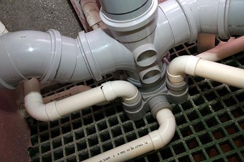
PIPEWORK MATERIALS AND JOINTS
A variety of materials are used for soil and waste pipework. They are covered by a number of different standards, as shown in the table below:
| Material | Standard |
|---|---|
| Soil pipework | |
| Unplasticised polyvinyl chloride (PVCu) – 110mm | |
| and 160mm diameter | BS EN 1329-1 |
| PVCu – 82mm diameter | BS 4514* |
| High-density polyethylene (HDPE) – 40-315mm diameter | BS EN 1519-1 |
| Modified polypropylene (PP-MD) 40-160mm | |
| diameter | BS EN 1451 / 1411 |
| Cast iron | BS EN 877 |
| Waste pipework | |
| Polypropylene (PP) | BS EN 1451-1 |
| Acrylonitrile butadiene styrene (ABS) | BS EN 1455-1 |
| Chlorinated polyvinyl chloride (PVCc) | BS EN 1566-1 |
Each material is jointed in a different way:
- PVCu soil pipes can either have a ring seal, which means they push-fit together, or they can be solvent welded
- HDPE soil pipes are jointed by electrofusion or butt-welding, which is quick and simple but requires the use of specialist equipment. Push-fit joints are also required to accommodate thermal movement
- ABS and PVCc waste pipes are solvent-weld jointed
- PP acoustic soil and waste pipes can only be jointed using the push-fit method
- Polypropylene waste pipes are push-fit jointed.
Branch pipes serving a single appliance should have at least the same diameter as the appliance trap.
DISCHARGE STACKS
Branch pipes connect to a central stack which discharges to a drain. When designing the stack, a number of factors need to be considered.
- Positive pressure. To eliminate positive pressure, the minimum distance from the base of the stack to the lowest branch connection varies depending on the height of the stack, as the table shows:
| Application | Minimum height |
|---|---|
| Single dwelling up to three storeys | 450mm |
| Up to five storeys | 740mm |
| More than five storeys | One storey |
| More than 20 storeys | Two storeys |
The stack base should use two 45˚ bends or a bend with a radius of 200mm or more.
- Stub stacks. Branch pipes can also discharge into an unventilated “stub stack” as long as they are only used to connect ground-floor appliances. The vertical drop to the drain must not exceed 1.5m from a WC and 2.5m from a waste appliance. The head of the drain should be vented to the atmosphere. The maximum loading of a stub stack is 5 litres/second.

- Ventilation. Discharge stacks need to be ventilated in order to prevent the water seal in the trap from being broken by a pressure build up in the system. A secondary ventilation stack is sometimes required to increase stack capacity due to the number of appliances connected. The table below shows the different options depending on the calculated flow rate of the system.
| Stack size (mm) | Vent (mm) | Maximum capacity (litres/second) |
|---|---|---|
| Primary ventilated stack | ||
| 82 | n/a | 2.6 |
| 110 | n/a | 5.2 |
| 160 | n/a | 12.4 |
| Secondary ventilated stack | ||
| 82 | 50 | 3.4 |
| 110 | 50 | 7.3 |
| 160 | 82 | 18.3 |
Another option is to specify an aerator, which eliminates the need for secondary venting by breaking the flow on each floor, thereby keeping the pressure difference well within the limit of 3mbar. A 110mm aerator can increase the stack capacity to 7.3l/s.
Branch pipes will not need separate ventilation as long as they do not exceed the length and gradient shown in the following table:
| Appliance | Maximum run (m) | Gradient (%) | Number of bends | Maximum drop (m) |
|---|---|---|---|---|
| Washbasin or bidet with 32mm-diameter pipe | 1.7 | 1.8-2.2 | None | 0 |
| Washbasin or bidet with 40mm-diameter pipe | 3 | 1.8-4.4 | 2 | 0 |
| Bath or shower | 3 | 1.8-9.0 | No limit | 1.5 |
| Sink | 3 | 1.8-9.0 | No limit | 1.5 |
| Washing machine or dishwasher | 3 | 1.8-4.4 | No limit | 1.5 |
| WC | No limit | 1.8 min | No limit | 1.5 |
| Sink disposer | 3 | 13.5 min | No limit | 1.5 |
If a branch pipe exceeds these limits, it should be connected via a branch ventilated pipe to external air or a ventilating stack, or an air admittance valve should be used.
An air admittance valve can be used to terminate primary vented discharge stacks, providing the air flow rate of the valve is at least eight times the peak flow rate on the stack.

- Size of stack. In order to work out the correct size of the stack for a specific system, the designer has to add up the number of discharge units and for each one apply a factor depending on the type of use – for example, a house, school or hospital. The procedure and calculation method are explained in Tables 2 and 3 and clause 6.3 of BS EN 12056-2.
- Prevention of cross-flow. A branch pipe should not discharge into the stack in a way that could cause cross-flow into any other pipe. To prevent cross-flow from a large-diameter branch into a smaller connection, the latter should join the stack in one of the following ways:
- Above the centre line of the larger branch
- At right angles to the larger branch
- At least 200mm below a restricted zone beneath the centre line of the larger branch. The depth of this zone is determined by the diameter of the stack: 90mm for an 82mm stack; 110mm for a 110m stack; 250mm for a 160mm stack.
- Offsets. Due to the design of commercial buildings, discharge stacks often need to be offset. When calculating the required flow capacity, the stack cannot be sized as a secondary ventilated system unless vent connections are incorporated on every floor. No connection is permitted within 450mm of the offset.
To book a CPD seminar at your office, email marketing@marleypd.com
How to take this module
UBM’s CPD distance-learning programme is open to anyone seeking to develop their knowledge and skills. Each module also offers members of professional institutions an opportunity to earn between 30 and 90 minutes of credits towards their annual CPD requirement.
This article is accredited by the CPD Certification Service. To earn CPD credits, read the article and then click the link below to complete your details and answer the questions. You will receive your results instantly, and if all the questions are correctly answered, you will be able to download your CPD certificate straight away.
CPD CREDITS: 60 MINUTES
DEADLINE: 28 AUGUST 2015
Privacy policy
Information you supply to UBM Information Ltd may be used for publication and also to provide you with information about our products or services in the form of direct marketing by email, telephone, fax or post. Information may also be made available to third parties. UBM Information Ltd may send updates about Building CPD and other relevant UBM products and services. By providing your email address you consent to being contacted by email by UBM Information Ltd or other third parties. If at any time you no longer wish to receive anything from UBM Information Ltd or to have your data made available to third parties, contact the Data Protection Coordinator, UBM Information Ltd, FREEPOST LON 15637, Tonbridge, TN9 1BR, Freephone 0800 279 0357 or email ubmidpa@ubm.com. View our full privacy policy at www.building.co.uk/cpd


No comments yet