


It is essential to understand the impact of thermal bridges if buildings are to be effectively insulated. This module, sponsored by Kingspan Insulation, explains how they occur, and how to reduce them

How to take this module
UBM’s CPD distance-learning programme is open to anyone seeking to develop their knowledge and skills. Each module also offers members of professional institutions an opportunity to earn between 30 and 90 minutes of credits towards their annual CPD requirement.
This article is accredited by the CPD Certification Service. To earn CPD credits, read the article and then click the link below to complete your details and answer the questions. You will receive your results instantly, and if all the questions are correctly answered, you will be able to download your CPD certificate straight away.
CPD CREDITS: 60 MINUTES
DEADLINE: 20 OCTOBER 2017


INTRODUCTION
When insulating a building, the impact of thermal bridges should be reduced wherever possible. The key considerations are the continuity of the insulation and the thermal conductivity of the chosen materials – materials with lower thermal conductivity extend the heat flow path and therefore reduce overall heat lost. Air permeability or airtightness is also important, as is buildability.
WHAT IS A THERMAL BRIDGE?
A thermal bridge can be defined as an area that has greater or lesser heat transfer than adjacent areas. When calculating the energy and emissions performance of a building, three types of thermal bridges are considered:
- repeating (linear and point)
- point (non-repeating)
- linear (non-repeating)
Repeating thermal bridges occur where there are regular interruptions within the building fabric, by materials with poorer insulating properties – for example, timber studwork or I-beams in a timber-frame wall construction, or fixings and fasteners. The differing (typically additional) heat flow incurred by a repeating thermal bridge is accounted for in the U-value calculation for the building element containing the bridge. These U-values are then used in SAP calculations.
Point thermal bridges are typically used as an adjustment to a U-value for an element, to take account of fixings or fastenings for example.
Linear (non-repeating) thermal bridging occurs at the junctions of a building’s planar elements (ie, between roofs, walls, openings and floors) and can add significantly to a building’s total fabric heat loss. Higher heat flows occur at junctions due to complex geometries, or from the use of materials with a higher thermal conductivity than the adjacent materials. This can cause localised reductions of internal surface temperature, which can lead to surface condensation and mould growth problems.
The differing heat flow attributable to the thermal bridge is typically, but not always, greater than that through the adjoining plane elements. This is the linear thermal transmittance of the bridge, measured in W/mK, referred to as a ψ-value (psi-value). The lower the ψ-value, the better the performance. ψ-values are not taken into account in U-value calculations, but they are included separately in the calculation methodologies used to assess the operational CO2 emissions of buildings. In the UK, SAP is used for domestic buildings, and SBEM for non-domestic buildings.

SAP AND LINEAR THERMAL BRIDGING
A building’s overall heat loss due to linear (non-repeating) thermal bridging is accounted for in SAP by the transmission heat transfer coe icient (or HTB), which is expressed in units of W/K.
To calculate this, individual thermal bridges are considered. First, the length, in metres, of each thermal bridge is multiplied by its respective ψ-value (see below). Then, the overall heat loss due to linear (non-repeating) thermal bridging is determined by adding the resulting figures together to give a value for HTB.
There are three possibilities for considering thermal bridging:
- Approved design details, for example as set out in the government’s Accredited Construction Details (ACDs). This involves independent assessment of the construction method. In this case, ψ-values from the approved column on Table K1 of SAP 2012 should be used, or from the approved source.
- uncalculated ψ-values: where some details are missing, the ψ-values from the “default” column in Table K1 of SAP 2012 can be used
- calculated ψ-values: values can be calculated by a person with suitable expertise and experience in accordance with BRE IP 1/06 and BR 497 (Conventions for Calculating Linear Thermal Transmittance and Temperature Factors). In this case, use the calculated ψ-values along with the length of each junction.
Alternatively, a combination of details and values from the three options above can be used. If no information is available, or if details are neither approved, nor calculated, then a global default value for overall heat losses associated with thermal bridging can be used. In such cases, a value of 0.15W/m2K is added to overall elemental losses, making it harder to achieve compliance.
In Scotland, a default value of y=0.15 cannot be assigned in a SAP calculation or EPC relating to a building warrant applied for on or after 1 October 2015. Calculation of heat loss through thermal bridges HTB must be undertaken. Also, the “Accredited” column in Table K1 cannot be used in Scotland. Instead, when following Scottish approved details, the calculated ψ-values accompanying each detail must be used.
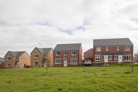
REDUCING LINEAR THERMAL BRIDGING IN CAVITY WALLS
Thermal bridging can be a particular issue for properties with cavity walls, one of the most commonly used construction types in the UK.
Thermal performance is not the only consideration when designing a building envelope. As homes become more energy efficient, it is essential to pay even closer attention to detailing in order to limit thermal bridging. Wall ties have typically been one of the culprits for bridging within cavity-walled constructions, though newer thermally broken wall ties can help to reduce this. These products are typically capped with a material that has a lower thermal conductivity than the metal tie. The application of tape to joints between the insulation boards within the cavity can also help to create more airtight properties, further improving building envelope performance.
Detailing at junctions should aim to minimise the effects of thermal bridging and the associated risk of condensation or mould growth. There are some simple design considerations that can be adopted to help mitigate the risks and reduce heat loss:
- For optimum thermal performance, care should be taken to ensure that, wherever possible, insulation is continuous. Where this is not possible, insulation layers should be overlapped and, ideally, insulation material introduced between.
- In a standard cavity wall-to-ground floor junction, the main linear thermal bridge is the inner leaf of masonry. This linear thermal bridge can be reduced by increasing the distance the heat has to travel, by overlapping the partial-fill cavity-wall insulation and the floor insulation. The key factor is the distance between the bottom of the cavity wall insulation and the top of the floor insulation (including any perimeter insulation upstand). In order to minimise cold bridging at the edge of ground floors, the distance between the top surface of the floor insulation or perimeter insulation upstand and the bottom of the wall insulation must be a minimum of 150mm for a concrete floor and 200mm for a suspended timber floor. The further that appropriate wall insulation extends past the floor insulation, the better the thermal performance of the junction between the wall and the floor.
- Perimeter upstand insulation is extremely important to minimise heat losses from the junction with external walls. This helps to increase the path of heat flow and therefore helps reduce losses through the junction. Omitting this, or using a poorer performing insulation for this purpose, can increase these losses.
- Using “lightweight” aggregate blockwork with better thermal performance on the inner leaf next to the junction can also lower heat losses, as can an internal lining of insulation on the warm side of the construction such as an insulated plasterboard.
- Prevention of thermal bridging should be considered when designing sills, jambs and lintels, and insulated cavity closers should be considered. Heat-loss from junctions around window or door openings can be further reduced by insulating the reveal. The key factor is the thermal resistance (R-value) of the insulation layer. Reveals should be designed to accommodate a minimum of 32.5mm insulated plasterboard.
- For junctions between external walls and roof constructions, continuity and overlap of insulation layers is the key to minimising heat losses from the junctions.
- To help limit thermal bridging and uncontrolled air-leakage via junctions in cavity-wall constructions, refer to product-specific modelling and calculated ψ-values – many of which are significantly better than the approved ψ-values given in column 1 of Table K1 of SAP for the ACDs that comprise partial and full-fill cavity-wall constructions.
How to take this module
UBM’s CPD distance-learning programme is open to anyone seeking to develop their knowledge and skills. Each module also offers members of professional institutions an opportunity to earn between 30 and 90 minutes of credits towards their annual CPD requirement.
This article is accredited by the CPD Certification Service. To earn CPD credits, read the article and then click the link below to complete your details and answer the questions. You will receive your results instantly, and if all the questions are correctly answered, you will be able to download your CPD certificate straight away.
CPD CREDITS: 60 MINUTES
DEADLINE: 22 SEPTEMBER 2017
Privacy policy
Information you supply to UBM Information Ltd may be used for publication and also to provide you with information about our products or services in the form of direct marketing by email, telephone, fax or post. Information may also be made available to third parties. UBM Information Ltd may send updates about Building CPD and other relevant UBM products and services. By providing your email address you consent to being contacted by email by UBM Information Ltd or other third parties. If at any time you no longer wish to receive anything from UBM Information Ltd or to have your data made available to third parties, contact the Data Protection Coordinator, UBM Information Ltd, FREEPOST LON 15637, Tonbridge, TN9 1BR, Freephone 0800 279 0357 or email ubmidpa@ubm.com. View our full privacy policy at www.building.co.uk/cpd


No comments yet