


The workflow for using BIM when adapting existing architecture is different to new-build projects. This CPD, sponsored by Vectorworks, explains how the organisational structure works
CPD CREDITS: 60 MINUTES
DEADLINE: 9 FEBRUARY 2018
For more information about UBM’s CPD distance-learning programme, click here

![]()
INTRODUCTION
BIM workflows are governed by many principles, but they will still vary from project to project and from one design team to another. Our advice has always been to “start BIM early”, using the parametric tools available to create both the geometries and data embedded in the model. This is true for both new-build projects and refurbishment projects. This CPD discusses the best practice workflow for modelling existing architecture, and how this workflow varies from that of a new-build.
BIM WORKFLOWS
BIM uptake in the UK has been driven by the UK government’s mandatory target of level 2 BIM on public sector projects from 2016. The key documents outlining how this should be done are the British Standards BS 1192, BS 8536-1:2015 and PAS 1192 parts 2/3/4/5. For companies, this has meant a steep learning curve and a cultural change, as they must work more collaboratively and move away from traditional, more insular processes. Sharing and reusing information, and being held to account for the data you provide in digital format, is a new world for many, requiring a significant adjustment in company processes and habits.
NEW BUILD VERSUS REFURBISHMENT
With a new-build project, it is possible to set up design layers, storey heights and organisational structures right at the very beginning. However, when dealing with existing architecture, it is first necessary to have a survey or digital representation of that environment. A plan can then be drawn from this information, with detail added progressively to the model. Once you have a better understanding of the building – for example, the facade arrangement, slab heights and thickness – you can create an organisational structure. When this is in place, new-build elements can be added and documentation extracted from the BIM model.
Capturing context
There are many digital processes that allow the user to accurately capture the surrounding environment using lasers and scanners. One method is to create a point cloud using a 3D scanner. Point cloud scans have become commonplace as the cost of technology has lessened. Hundreds of thousands of points with a three-dimensional coordinate value (typically X, Y, Z) and RGB (colour) value can be imported with relative ease. This process does not create a 3D solid model, however, so there is still a manual process of drawing over the model to create geometry.
Another digital means of capturing context is photogrammetry. This technology creates a 3D solid model from 2D images or frames from a video. There is far less manual interaction required as the software automatically calculates the location of features relative to other features. This approach is particularly effective for period buildings with varying patterns and textures. Recording devices attached to drones can capture huge areas of landscape by simply following the predetermined flight path. This process requires much more computing power and so sufficient processors are required for the task.
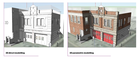
Direct modelling versus parametric modelling
Direct modelling allows the designer to quickly define geometry using commands such as “push/pull”, “extrude along path” and “taper edges”. This is a great tool for concept modelling as little effort is needed to create 3D objects. Parametric modelling requires more upfront planning and results in an object that can be altered using data fields. Constraints are created and these govern the geometry of the model.
Design software also includes preset parametric objects, such as walls, slabs and doors in various styles, which are ready for use on any project. These come with IFC data attached, so that when exporting these objects to view in other BIM packages, semantic relationships are upheld and both the geometry and data is maintained – for example, so windows are recognised as windows and not just “dumb geometry”.
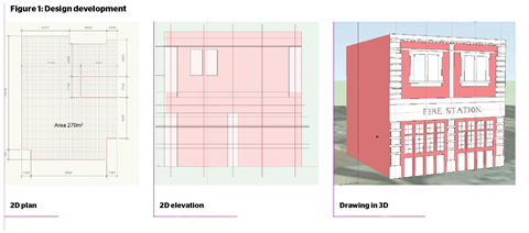
The flexibility of direct modelling complements rule-based parametric modelling systems and the two are often used in conjunction. Figure 1 shows the transition from 2D, to 3D extrudes, to parametric walls and windows.
File setup
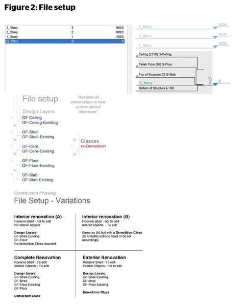
The file setup will vary between projects, depending on the size and type of building, which company is responsible for which parts of the building and how many people work in each team. In addition, it will include the correct coordinates for the location of the site and building. The example in Figure 2 of a design layer structure enables the designer to include various spaces and systems within the same model.
The Slab layer is where the structure sits and is the 0 Datum for the floor. The floor finish and furniture are on the Floor design layer, stairs and lift in the Core and external facade on Shell. With this arrangement, areas of the building can be worked on and documented individually. Storeys are a BIM level 2 requirement. The relationship between these and Design Layers can be seen below.
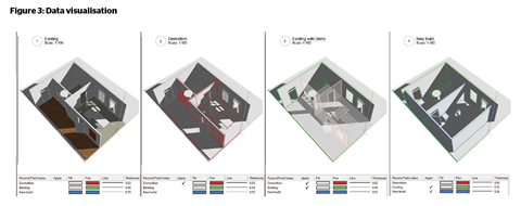
Data visualisation
BIM models are data-rich environments, and the data visualisation tool within BIM software allows the designer to visually represent this data. The example shown in Figure 3 is for construction phasing, showing existing, demolition and new-build elements in one drawing. This is achieved by:
- having the proper file setup
- creating a data record for existing, demolition and new elements
- colouring elements with a particular data record using data visualisation.
This tool can be used for a wide range of tasks, including colouring buildings based on height and rooms based on net area. Data visualisation is only available in viewports (presented on a finished drawing sheet, rather than directly in the working model) but the number of possible applications is limitless.
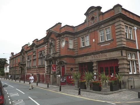
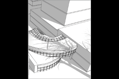
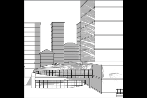
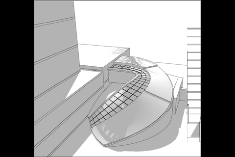
Below: This double-curved, free-form structure – a modern extension to Windsor fire station – was created in Vectorworks, using the following conceptual modelling tools: Nurbs Curve, Loft Surface, Split Faces, Surface Array, Shell Solid. These tools can enable the user to create geometries not possible in a 2D environment

How to take this module
UBM’s CPD distance-learning programme is open to anyone seeking to develop their knowledge and skills. Each module also offers members of professional institutions an opportunity to earn between 30 and 90 minutes of credits towards their annual CPD requirement.
This article is accredited by the CPD Certification Service. To earn CPD credits, read the article and then click the link below to complete your details and answer the questions. You will receive your results instantly, and if all the questions are correctly answered, you will be able to download your CPD certificate straight away.
CPD CREDITS: 60 MINUTES
DEADLINE: 9 FEBRUARY 2018
Privacy policy
Information you supply to UBM (UK) Ltd may be used for publication and also to provide you with information about our products or services in the form of direct marketing by email, telephone, fax or post. Information may also be made available to third parties. UBM (UK) Ltd may send updates about Building CPD and other relevant UBM products and services. By providing your email address you consent to being contacted by email by UBM (UK) Ltd or other third parties. If at any time you no longer wish to receive anything from UBM (UK) Ltd or to have your data made available to third parties, contact the Data Protection Coordinator at ubmidpa@ubm.com. View our full privacy policy at www.building.co.uk/cpd


No comments yet