


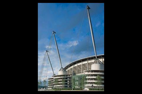
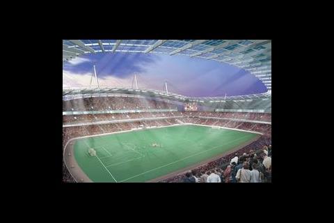
The nature and extent of this servicing can come as a bit of a shock to the rest of the design team, but in the case of the Manchester's new stadium the full integration of systems from inception creates a calm building, clear of visible services in public areas and still satisfying the flexibility demands of a modern international stadium. Not forgetting of course, that after the Commonwealth Games the 38 000 seat stadium will be transformed into the 48 000 seat home ground for Manchester City football club. Easy on the eye but complex in achievement is the theme for this building.
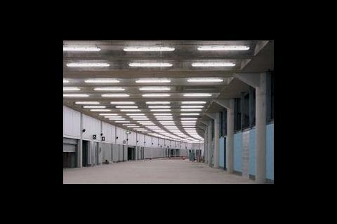
Services distribution in particular is a thorny issue for all stadia due to the disparate location of the areas which need servicing. The semi-industrial quality of these buildings historically precludes the use of concealing finishes. However, the integrated way in which the team worked together in this case has meant that the architectural design has been configured in sympathy with the needs of energy load centres. This has achieved the team's aim for a concourse substantially without visible services, initially and during the life of the building.
Methods to achieve these objectives during the life of the design process included many grand schemes.
There was an idea for a full access road beneath the stadium, incorporating significant subterranean plant room areas and using ramp towers to intake and exhaust air. There were various investigations of plant locations within the building.
However, a much simpler and more appropriate scheme was finally developed using the architectural and structural ramp towers to house central plant, with a buried services raceway around the perimeter of the stadium. This raceway distributes electricity, water, gas, heating water and communications services under the concourse paving around the outside of the main building in a U-shaped construction.
The ramp towers, being circular, would not be the services engineer's first choice for shape, but because of their significant diameter they accommodate all the principal plant. This made effective use of spaces which would otherwise be voids.
Plant with larger distribution systems, such as air handling units, are located local to the point of use and on the plant decks above the accommodation wings.
The 9 m diameter cores house all major shell and core primary plant, in tiered plantrooms, housing equipment such as boilers, water storage tanks, pumps, generators, hv equipment, transformers, lv equipment, emergency lighting static inverters and central batteries.
The towers have stringent structural needs ultimately carrying the mast and roof loads. Added to this complexity was the desire to maintain the 'drum' walls free from louvres to other types of penetration.
Primary penetrations were therefore located at the highest level within the structural 'cone' supporting the masts and through depressed pile caps feeding the services into the ground and the service raceway.
The integrated plant rooms and services raceway proved themselves during several value engineering exercises to be very cost-effective.
Service raceway
The raceway links the primary services from the ramp towers to the major vertical building services cores. Also across the link bridges, the raceway forms a U-shape around the south side of the stadium – connecting the covered roadway into the basement and the north stand area which will be excavated post-games. This minimises risk of accidental damage during the second phase of construction. Access to each quadrant core is through the building perimeter above depressed pile caps.
Pre-insulated cross linked polyethylene pipe with a protective outer hdpe sheath is used for the lphw heating distribution. Cold water distribution is run in cement lined ductile iron pipe to remove the risk of tainting the water due to the existence of ground contamination. There are over 40 km of armoured cable distributed around the raceway and feeding power boards.
Future flexibility
The phasing of the athletics and football modes created some challenges to the building services strategy. In particular, the construction of the north stand and the two shell and core fit-out packages – Commonwealth Games and Manchester City football club. With so much of the fit-out for concessions and hospitality areas falling outside the original remit services engineers had to ensure that the clean concourse approach would not be compromised.
Concept design and indicative schematics were prepared for all services, dotted with the anticipated services. Fortunately, Arup were appointed to carry out this design work directly for Manchester City football club and the original allowance made proved to be generally of the right order. Space was allocated at upper levels (plant deck level) to accommodate toilet extracts, provision for catering exhaust, chillers, floodlight control panels and the like.
Concourse and ramp lighting
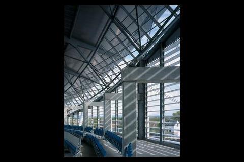
Working closely as an integrated team brought many advantages to the design process and end result. Perhaps the one issue which demonstrates is was the lighting of the main internal concourse areas.
During the early scheme design stage the structural design was for a waffle construction within the concourse areas, with luminaires, pa/va speakers etc located in the waffles. This would result in some dark patches and shadows on the soffit due to the artificial lighting. To demonstrate the appearance computer generated models were created using Lightscape software. The result of the modelling demonstrated to the team that the proposed structure and lighting combination was unsatisfactory. As a result further modelling of options was undertaken and a beam and coffer solution, with integrated service trays containing luminaires, pa/va speakers etc, selected. So the structure is configured to be sympathetic to the architectural and artificial lighting needs and overall gives a striking, clean, bright and welcoming appearance. A similar exercise was carried out for the walkway ramps around each of the towers.
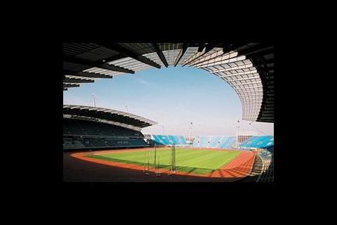
Roof drainage
The entire bowl roof area of 22 000 m2 is drained in two locations. The roof slopes backwards and rainwater is collected in circumferential drainage channels running from the high points on the east and west stands to the two low points in the north and south stands. At these points the water is discharged into inclined steel chutes (2·4 m wide by 20 m long) which discharge rainwater into exposed collection sumps. The peak storm condition generates approximately 450 litres/s of rainwater down each of the chutes. The chutes were developed within the team to be both functional and an architectural feature.
Boiler flues
The installed boiler load is 3·7 MW (output), the dispersal of the products of combustion gave the team another challenge to resolve. Several options were considered. The flue gases needed to be discharged well above the level of spectators in the adjacent stand. Suggestions ranged from utilising the inside of the masts supporting the roof structure to attaching flues to the mast structure, none of which could be structurally or architecturally solved in an acceptable manner. The chosen solution was a flue dilution system with separated intakes and discharges at the roof of the tower shielded from view by the structural crown supporting the mast.
Lighting
The event lighting has been designed to comply with the requirements of FIFA, CIE67 and CIE83. Over 200, 2 kW floodlights are switched individually allowing a range of uniform lighting levels to be achieved on the playing surface ranging from 100 lux for ball training exercises up to 1400 lux for televised international matches. A proportion of floodlights have hot re-strike control gear and these are backed-up by the standby generators in order to maintain 800 lux as the minimum for television to continue live coverage in the event of a normal mains failure. Thus providing surety of television revenue income, at least from a technical point of view.
During an event the generators will be run to serve the hot re-strike floodlights. Should the generator fail the supply will automatically switch to the normal mains without disruption to the lighting.
In the event of both normal mains and local generator failure then the generator in the opposite stand will serve the essential stand lighting to enable safe evacuation of the stadium to be carried out. In addition emergency lighting from inverter central battery units is also available for safe evacuation should both mains and generator supplies have failed. It will take something extraordinary to loose the lights.
The floodlights are mounted under the roof in a special designed roof 'kick-up' profile which assists in preventing light pollution and provides easy access from the roof for commissioning and maintenance. The 'kick-up' provides an integrated solution incorporating the floodlights, house and emergency lighting and pa/va system with safe access for maintenance from the top side of the roof avoiding the requirement for costly, unsightly gantries which would in themselves create ideal roosts for local pigeons.
Anyone who has travelled into Manchester Piccadilly rail station will have seen the stadium as a proud landmark. This is further enhanced at night through the combination of blue led lamps at the top of each of the 12 masts (up to 75 m high), around the roof edge and the floating effect of the roof through floodlighting to its underside.
The towers are provided with white rings of light from circular luminaires wrapped around the spiral walkways. This sets the scene when all feature lighting are illuminated the stadium appears as a spectacular backdrop against the Manchester skyline.
Fire safety systems
The means of escape determined that the public concourse areas were sterile and places of relative safety. However the concourse spaces also provide the main concession spaces for the spectators to purchase goods, food and refreshments so there needed to be a mechanism to deal with fires, should they occur. The traditional method for addressing these issues is to use sprinklers and smoke extract systems. Two issues concerned the design team with sprinklers: the cost and the frost protection of all the pipework in the unheated, naturally ventilated concourses.
Through close working with all parts of the design team and building control a novel solution was developed. Simply, each concession unit comprises a double fire rated roller shutter assembly with the inner (concession side shutter) reaching the floor and the outer (concourse side) shutter stopping short of the floor. An extract duct is connected at high level into the void between the shutters creating a negative pressure and ensuring that any smoke escaping through the concession shutter does not enter the public domain and cool concourse air is mixed with the smoke/heat to reduce the extract air temperature. The smoke extract ducts are connected into the general toilet extract systems. The ductwork did not need to be fire rated as calculations showed that the smoke temperatures would be sufficiently cooled by the ambient air drawn from the concourse. The run/standby toilet exhaust fan arrangements are served from an essential power supply source.
Dealing with the basement area also resulted in a novel solution. While the basement storey in the west stand is open to the pitch and service tunnel levels it was considered appropriate to provide some additional protection to assist in fire fighting operations in this area.
Natural ventilation of this is not readily achievable due to the limited locations that could be used for venting and the potential detrimental impact from prevailing winds. Mechanical ventilation from the entire basement would require sprinklers throughout the basement. Therefore a mechanically assisted air exchange system in the corridors is provided. This system will be used by the fire service to clear smoke from the corridors by purging them with fresh air with selected doors opening automatically during its operation, through which any smoke will be flushed.
Facts and figures
- Power is served to the stadium via two 2 MW substations, through 11 kV medium voltage switchgear and two 1 MVA transformers.
- Two 0·5 MVA generators provide power for essential and emergency television lighting services.
- There are 42 air handling units and over 170 extract fans.
- Over 16 km of cable tray/basket.
- The first stadium in the country to fully comply with current FIFA lighting standards.
- More than 8000 luminaires.
- 3·7 MW boiler capacity.
- First stadium to pioneer a bespoke intelligent lighting control system for the entire stadium.
- 1·5 MW heating provision for under pitch air heating system (0·5 MW fan motor).
- Over 40 km of armoured power distribution cable.
- Full compliance with the Green guide FIFA, CIE83 including 25 lux emergency lighting level on the terraces and escape concourses.
- Machine-room-less lifts.
- Requirement for sprinkler protection designed out.
Source
Building Sustainable Design
Postscript
Andy Woodhouse is associate director with Arup.
Overall design of the stadium for all engineering disciplines and architecture is by Arup.

No comments yet