As project managers and lead consultant for BT's computer and data services centre in St Albans, Hertfordshire, Roberts & Partners was required to design building services for system reliability, energy efficiency, on-line maintainability and no single points of failure. The designers were also mindful that the 0·02% allowance for failure only covered computer glitches, not services shutdowns.
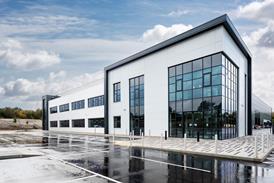
The architecturally uninspired building was constructed specifically as a computer centre in 1980. In the late 1980's part of it was mothballed, to be resurrected in the 1990's as a data processing centre.
It houses four main computer suites: the main hall, with a design loading of 1000 W/m2, two communications rooms with a design loading of 600 W/m2, and a media room (200 W/m2). The main hall and communications rooms are located on the first floor while the media room resides on the ground floor.
The building services infrastructure has been designed to meet these loads, although the design can accommodate additional plant without interrupting the service. Fortunately, plant space was generous and well located. Underfloor voids in the computer areas were also sufficient for air distribution and engineers' requirements once the floors themselves had been replaced.
Refrigeration design
BT's computer suites usually rely on direct expansion (dx) refrigeration. In this instance though, Roberts & Partners felt that better temperature control and improved efficiency could be achieved using a modular central chiller and a chilled water system – even though this would require careful design to maintain the system's robustness.
BT's main concern was that a single weld or chilled water pipe failure would mean losing the entire system and consequently the computer centre. Roberts & Partners' solution was to design a two-way chilled water ring main with additional isolating valves between each take-off, thus creating two paths to each terminal.
This approach enables any section of the system to be isolated, drained-down and repaired without losing more than one terminal unit (see figure 1). The only drawback with this approach was that if one part of the system is isolated, the chilled water flows and system hydraulics change, which upsets the balance of the circuit.
To overcome this problem, Roberts and Partners fitted two-port valves on each terminal unit, and used variable speed secondary chilled water pumps.
The two 700 kW Climate chillers have been sized to provide a 100% standby capacity. Should one chiller fail, the controls have been configured for a replacement to run alongside the existing chiller while its performance is monitored. Each chiller incorporates four Hitachi screw compressors with independent refrigeration circuits. A Trend microcontroller links the circuits and by default becomes the weak link in the chain – the single point of failure for the chiller.
To get round this, the controls have been duplicated with a standby outstation bolted to the side of each chiller. A thermostat in the return switches between the two panels if the return water temperature goes more than 38C above the norm, activating the four compressors in eight, temperature controlled stages.
Dedicated Guntner's condenser units, sited on the roof of the building, serve the compressors. Like everything else on this project, the condensers have two circuits, although in this instance one serves a glycol/water free cooling system while the other is a refrigerant condensing coil.
The engineers were only interested in sensible cooling for the computer rooms. This enabled them to opt for higher than normal chilled water temperatures of 148C flow, 208C return, so improving efficiency. It also gave them the chance to use free cooling when external temperatures drop below 138C, a not infrequent occurrence given the centre's 24 hour operation. When external temperatures are less than 88C the engineers anticipate the site's total cooling load can be met entirely by the free cooling system.
In assessing the potential for free cooling, the bems takes the cooling characteristic of each condenser. It then measures the secondary chilled water flow rate and the chilled water flow and return temperatures to calculate the building's load. If, on comparison, the free cooling available exceeds the building's load, the bems disables the compressors and initiates the free cooling system.
The free cooling circuit also has a coil buried in the car park to dump heat into the ground. This brings the bonus of keeping the car park free of surface ice. Inherited from the site's previous cooling system, this was incorporated into Roberts & Partners' scheme.
Ventilation
The chilled water feeds nine vertical ahus which supply cooled air directly to the adjacent computer hall and communications room floor void. Air is ducted from the hall's ceiling void and returns to the plantroom, which acts as a giant plenum at high level. Jet spray humidifiers condition the supply air before it is drawn into huge 1 m diameter single-inlet, backward-curved centrifugal fans mounted on top of the ahus. Room design conditions are 228C±28C, with 50% rh ±10%.
Each fan can provide up to 84 kW of cool air while absorbing less than 6 kW of fan power. Inverter drives ensure the standby unit fans run as well as the duty units, with a subsequent reduction in the fan speed for all units and another efficiency improvement.
Control problems resulting from inverter drives on both chilled water and air systems were avoided by giving the pumps the lead. A water to water heat pump takes heat from the chilled water return at 208C and converts it into low grade hot water (lghw) at 518C.
Potentially, 300 kW of heating is available for use in the underfloor office heating system and to preheat domestic hot water. The heating also serves two fresh air ahus (duty and standby) which are used to pressurise the computer hall, communications rooms and media hall to 30 Pa, preventing contaminant ingress. A small dx coil in each ahu provides the cooling and dehumidification.
Roberts and Partners' designer Nick Vaney claims that overall energy savings, when compared to a traditional dx and electric heating design, are in the region of 75%. The reduction in CO2 emissions is also claimed to be in excess of 2300 tonnes/y.
Electrical design
The electrical design has been approached in much the same way as the mechanical services, that is, the omission of all single points of failure in the system. Two 1·5 MVA power strings feed the building with standby power provided from an additional 2·5/2·0 MVA string.
The electrical distribution system incorporates Broadcrown standby diesel generators and Anton Piller 625 kVA rotary ups modules in a parallel redundant configuration. Form 4 switchgear and dual power supplies feed all critical items of plant.
All the equipment can be bypassed without disrupting day to day operations. Overall, the system used means that BT's bosses shouldn't lose sleep over the building's services.
Source
Building Sustainable Design
Postscript
Andrew Pearson MSc is a reporter on Building magazine.