


This task was set for lead engineer Nicholas Howard of Arup and his team, in collaboration with architects Pringle Richards Sharratt, by Oldham Metropolitan Borough Council, who wanted to build a gallery on a former gasworks site in the town.
"We started on the design around August 1999, and we worked together with the architects right from the beginning. Remediation work began in January 2000 and the project was finished by December 2001, so we were on site for less than 24 months," recalls Arup's Howard.
"The programme speed made it a real challenge. We only started in January and by July we were tendering the services. So we went from nowhere to having a very cohesive scheme in a short space of time, but it was difficult," he adds.
John McLaughlin from Pringle Richards Sharratt agrees: "It was hard to meet the time scale and it probably wouldn't have worked if we hadn't collaborated. Building to be sustainable means everyone has to work together. The engineers and the architects need to have a common goal."
Work finished on the site at the end 2001 and the gallery opened to the public in February 2002. The building houses a number of contemporary art exhibitions as well as displaying works from the permanent collection owned by the council.
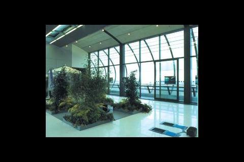
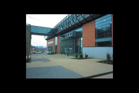
The finished gallery is impressive. Set on the outskirts of the town centre it is three storeys high and has an education room, glazed reception area, and bar on the ground floor, and several gallery and office spaces on the first and top floors, complementing the existing galleries in an adjacent building connected via an enclosed walkway.
"The exhibitions are not permanent and will change from time to time, so Oldham wanted a design that offered maximum flexibility in all spaces, which meant we had to think hard about our strategy," explains Howard.
"As the site was contaminated we couldn't afford to build a large basement; removing the contaminated earth would have been very expensive. We decided to have a small basement where we installed the boilers, water tanks and electrical switchrooms, which kept the cost down."
A decision was made to install the gallery air plant locally. On each of the three main gallery areas on the top floor there is plant nearby, which meant the distribution of the ductwork wasn't all the way from the basement, providing economy of space in the risers.
With only a limited budget of 12% of the total cost set aside for the m&e services the design team needed to think of a way in which they could service the spaces without too much mechanical assistance. This was complicated by the fact that there were strict parameters set by the Museums and Galleries Commission on temperature and humidity control to protect the precious exhibits.
Maintaining conditions
The building has effectively three different grades of space (figure 2). The first level being the basic accommodation, such as the reception area, education space and bar, these spaces are primarily naturally ventilated through the opening of windows. The second level of conditioned space is the normal gallery area and offices, sited on the first and top floors, and has tight temperature control. Temperatures of 16°C to 26°C have to be maintained at all time with no more than a 4°C change in 24 hours. The office area can be upgraded into gallery space in the future as it is served from the same ahu and air-cooled chiller as the gallery above.
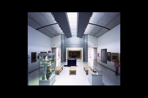
The third level is the tightly controlled gallery space on the top floor and the fine art store below (see figure 1). Here temperature and humidity levels are kept under check. This gallery also has an air-cooled chiller, coupled with air handling units in mezzanine plant rooms. Additional humidification is provided with a duct mounted system.
The other gallery spaces have an upgrade route whereby humidity control can be provided to give the same tight control as the high specification spaces. "We wanted to provide spaces that offered Oldham maximum flexibility, so the gallery could display a range of exhibits from sculpture to far more sensitive works, explains Howard.
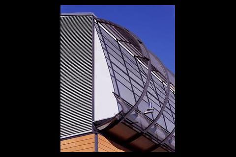
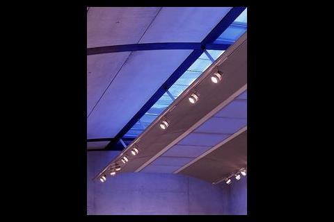
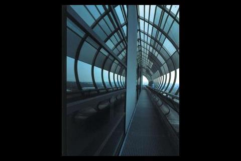
Air supplies to the building are ducted to the supply grilles through the floor void. It was decided not to use a plenum as the supply conditions are too onerous and a plenum would remove the level of fine control required. Air is extracted from the gallery spaces at high level within a glass duct. The duct performs a number of functions and is the product of close collaboration between the engineers and the architects. It allows natural light into the space, an extract path for the air and, through the incorporation of a slated walkway and security grillage above, a means of eliminating direct sunlight from entering the galleries.
Below the extract duct sits the 'light wing', which runs the length of the building and provides another neat combination of functions. It provides additional shielding from direct sunlight penetration, bounces light off the vaulted soffit of the gallery, and is home for the luminaires.
Ventilation at ground level is achieved through openable windows, with blinds to reduce solar gains in the summer. The primary task of the air conditioning in the galleries is to safeguard the artwork, although this also makes the spaces thermally acceptable to the occupants.
Heating to the building is split: galleries at either end are heated with an all air system from the air handling units, which is fed by low temperature hot water from the basement boilers; the central gallery has two packaged heat pumps, with 100% fresh air for the potential high occupancies within this space.
The basement boilers are conventional fan-flued boilers providing 210 kW. This allows the gallery spaces to be completely free of any water-based systems – even the rainwater pipes from the roofs are kept well away from the sensitive gallery areas.
Trench heating is sited along the edges of the building on the ground floor and within the gallery lobbies on each level. The foyer area has additional under floor heating. "We added under floor heating because of the large glazed areas," explains Howard. "It's a transient space and we didn't want people to come in and feel the cold radiation from the glass. Putting in under floor heating offsets this effect. We also put in trench heating around the edges to stop downdrafts from the glazing."
In the event of failure
Providing an adequate safety system in case of emergency was particularly challenging with only a small budget available for m&e. This problem was compounded by the fact that any system design would have to meet the strict criteria set by the gallery's insurers.
"The insurers have stringent restrictions on what you can and can't do. We met with them and put together a holistic strategy that would meet the criteria they wanted," explains Howard. "We designed so that in the event of an emergency or a power cut we shut all the doors and let the thermal capacity of the space moderate the conditions.
"The insurers were happy with this sustainable approach, because it's not so much the temperature or humidity at which the artwork is stored that is the issue, it's the rate of change in the conditions that causes the problem.
"We analysed the spaces and found that by using the thermal mass of the structure we could keep the rate of change to within the Museums and Galleries Commission requirements of no more than 4°C change in 24 hours and 10% in relative humidity."
Using this approach to regulate conditions meant the building needed to be airtight. "The Commission stipulated that the building had to be well sealed and we specified that air leakage should be no more than 2 m3/h/m2 envelope," says Howard. To ensure this requirement was met the designers invited BRE to conduct a pre-inspection to identify areas of weakness and then a full air tightness test.
Lighting in the building has been designed to allow for flexibility and can be adjusted to suit any type of exhibition. For example, the main galleries on the top floor are naturally lit via the light wing on the roof, with dimmable and adjustable spotlights fitted to supplement light levels and help with scene setting.
"We were told in the brief to offer as much flexibility as possible," says Howard. "Using spots allows for that. It also helps to protect the artwork because it is possible to redirect the light away from the work if needed."
Plans are already in place for phases two and three of the development. Phase two would see the construction of a new library on the site of the car park situated to the rear of the building, while phase three would see the refurbishment of the attached existing building.
Oldham Art Gallery, Union Street, Oldham, Lancashire OL1 1DN
AHUs: PM Luft
Boilers: MHS
Chillers: Trane
Control valves: Sauter
Above ground: Glynwed Ensign Soil and Geberit HDPE rainwater
Below ground: Glynwed Cast Iron
Dry riser inlet boxes: Thorn
Packaged air systems: Carrier packaged heat pumps
Floor grilles: Wade
Hot water calorifiers: Heatrae Sadia
Humidifiers: R Tech (Humidification)
Pumps: Pullen
Pressurisation tanks: Pullen
Underfloor heating: Wirsbro
Water boosters: Pullen
Controls: Detail Design Engineering, Trend
Lifts: Oakland
Luminaires: iGuzzini, Wila, DAL, Illuma, Sill
Motor control centres: Hech Engineering
Gross floor area (gfa): 2900 m2
Tender date: services July 2000
Form of contract: Management contract
Contract period: 22 months
Was National Engineering Specification used on this project? No
Winter: -4 °C/Sat
Summer (a/c): 28°C db, 19°C wb
Galleries: 16°C 26°C ±1°C.
40% to 65% rh ±5%
Slab thickness: 200mm with downstand beams
Clear floor void: 450mm in top galleries
Floor to ceiling: Varied up to vaulted ceiling at 6·8 m
Live load: 4 KN/m2
High occupancy gallery: 1 person/m2
Galleries: 6 person/m2
Offices: NR 30 in galleries
Fabric leakage
2 m3/h per m2 of envelope @ 50 pa
Installed heating load: 207 kw
Installed cooling load: 124 kW
Gallery fine art store ahus at: 2·4 m3/s
Central gallery packaged heat pumps: 2 no at 0·84 m3/s
LTHW: 80°C flow, 60°C return
DHWS: 65°C flow, 55°C return
Chilled water: 6°C flow 12°C return
Refrigerant: R134a
kVA transformers 500 upgradeable
30 Person hydraulic side acting rams 1 no 3000 kg, 1 no 5000 kg
Building services total: £985 000
Total cost: £8.25 million
Source
Building Sustainable Design
Credits
Client Oldham Metropolitan Borough Council Management contractor Mowlem Architect Pringle Richards Sharratt M&E consulting engineer Arup Structural engineer Arup Civil engineer Arup Geotechnical engineer Arup Quantity surveyor Davis Langdon and Everest M&E contractor Drake and Scull Commissioning contractor Comtech

No comments yet