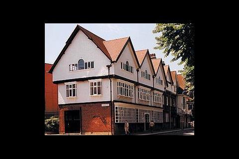
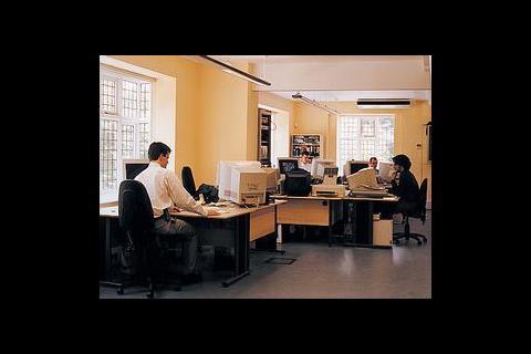
The new premises are set in a Grade II listed building providing 505 m2 over four floors. The basement of the new building contains a BT equipment room, air conditioned server room and secure store. The ground floor houses a system administration room, a reception and waiting area, a meeting and demonstration room, along with the boiler room, and toilets. A large open plan office area takes up most of the first floor, which also houses a meeting room and a kitchen. Finally the second floor contains the two directors' offices, the office reception area, directors' meeting room, an office administration room, kitchen, toilets, and a shower.
A mix of high frequency fluorescent luminaires, tungsten lamps, and low voltage halogen lamps provides lighting throughout the building. Emergency lighting comes from maintained emergency fittings with self-contained battery and inverter packs. Security is provided for the ground floor windows by eight shutters. There are separate security and fire alarm systems.
Air conditioning is supplied throughout the occupied part of the building by ceiling mounted fan coil units linked to two external heat exchangers. A separate system, comprising two independent units and a standby unit, provides air conditioning to the main server room in the basement. The heating system consists of an existing boiler and trv controlled radiators.
Services and security working together
As part of the refurbishment of the Bath Road premises, AL Digital required that the building services and certain elements of security should be controlled by an open building control system. The non-proprietary system should be based on a published, standardised control and communications protocol. For the system as whole, components should be available from a range of suppliers, to avoid single supplier lock-in. The working space in the building will provide a range of uses. To accommodate these, as well as future changes and enhancements, the building services and security systems were required to be quickly and easily reconfigurable, without incurring substantial costs. The control system chosen was European Installation Bus (EIB).
EIB is an open protocol system that uses a supplier-independent software tool called ETS, which is essential for every EIB project and device. The software provides the toolbox for installation, and is for use by designers and installing contractors. The ETS software is the foundation of EIB's flexibility, allowing easy and cost-effective initial design and reconfiguration of building services installations without the cost and disruption of hard rewiring.
EIB is an event-controlled system. The backbone is the bus line, which is usually a twisted pair instrumentation and control cable that runs throughout the installation. Sensors and actuators link to the bus line through bus-coupling units (Figure 1).
Once connected and programmed, all devices can exchange information, transmitted serially according to fixed rules (the bus protocol). This involves packing the information, or data, into a telegram, which is transmitted through the bus to one or more actuators.
For example, a light switch and a light sensor might switch or dim certain lights. The same sensor might also communicate with the blinds on windows, sending messages to close or draw the blinds in response to daylight changes.
For this to work all sensors and actuators have a physical address. Commissioning and programming decide which sensors communicate with which actuators. Sensors can communicate with one or a group of actuators.
In any one system more than 12 000 devices can communicate with each other. Each device is assigned a structured address, analogous to the postal system. The hierarchy for an EIB installation is:
- 64 bus devices form one line
- 15 lines form one area
- 15 areas form the complete system
Control system specification
At Bath Road, the requirements for the EIB building control system included lighting, heating and air conditioning.
For lighting, local manual switching and dimming was specified for the lighting, with extensive central and multi-way switching. Some push-buttons forming part of multi-way circuits were required to be programmed so that they could only switch on certain lights and not switch them off – for example lights that had already been switched on by someone else using the stairs. For the meeting and demonstration room facility the control system needed to provide scene setting, using pre-set or locally programmable controls. The three external lighting circuits were to be both manually controlled and responsive to daylight.
Security
The control system was to provide manual raising and lowering of the eight security shutters. This was to be achieved through central and multi-way switching, with three modes of push-button operation (described later).
An interface was required to the building's main security panel and to the electronic locks of the front and rear doors. On exiting the building the EIB control system was to switch off all internal electrical circuits and the porch light (leaving on two of the exterior light circuits) and lower the main entrance shutter. First person entry to the building would raise the main entrance shutter and switch on the lights in the entrance area of the building.
For the heating and air conditioning, the boiler and pump circuits were to be controlled by a simple time switch, with timed pump run-on when switching off the boiler. There was no need for control of the air conditioning system as this consisted of individually controlled fan coil units mounted in the ceiling. However, EIB bus cable was required to be run alongside all the fan coil units as well as the existing radiators so that it would be easy to add EIB control and fault reporting at some time in the future.
The EIB control system was implemented using a variety of sensors and actuators. The sensors include push-button switches, a daylight sensor and volt-free contacts on the security panel and the front and rear door locks. The actuators consist of general purpose switches; dimmers for tungsten, low voltage halogen, and high frequency fluorescent lamps; and shutter controllers. Logic controllers are needed for the interface to the security system and some on-only switching. System devices consist of a power supply unit and a line coupler on each line, and a pc interface unit (which can be attached to either line). The pc interface unit links the EIB bus to a pc for testing purposes (or real time computer control), and so that application programs can be downloaded to EIB devices.
Altogether there are 97 addressable EIB devices in the system: 59 on-line one and 38 on line two. The two lines are linked by a third line (line zero, with its own power supply unit) which has been reserved for future expansion (Figure 2).
Push button switches
Push button switches operate the lights, shutters and other circuits, and have two, four or eight push-buttons finished in stainless steel. The devices are very versatile and can be programmed to act as general purpose switches, to switch and dim lighting, or to operate shutters.
A button can be programmed so that a short press switches a light on or off, and a long press dims the light. Moreover the push-buttons can be set to work individually (for example toggling between on and off with successive presses) or to work as a pair (one as the on button and the other as the off button).
Lighting
For light switching, single push-buttons are programmed to toggle between on and off. For dimming, two separate push-buttons are configured for dimming up and dimming down.
The actuators include a number of 500 W dimmers for tungsten and low voltage halogen lighting, 2·3 kW (1 V to 10 V) dimmers for high frequency fluorescent lighting, and a mix of six channel 6 A, four channel 10 A and four channel 16 A switches for switching only. All the actuators are mounted on DIN rails in cabinets.
Central switching (where a number of different lighting circuits are controlled by one central push-button or other sensor) and multi-way switching (where one lighting circuit is controlled by a number of push-buttons or other sensors in different locations) can be implemented very easily in EIB, and both are used extensively at Bath Road.
An example of central switching is the use of the security panel to switch off all the internal circuits (and to close the main entrance shutter) when the building is vacated. The rear lobby lights are an example of a multi-way circuit – as well as centrally they can be switched from three staircase landings and the reception desk.
The on-only switching in some multi-way circuits is implemented using a single logic controller. This controller can be configured in various ways: for example as one 8-input logic gate, two 4-input gates or, as at Bath Road for the on-only switching, as two filter/ timer modules.
The light mood control in the demonstration room is implemented with an eight-button unit that can switch/dim eight independent lighting circuits, and provide eight different moods (set locally or pre-programmed from the pc) simply by pressing one of the eight buttons.
LED indicators on some push-buttons show the status of lights that cannot be seen from the operating position.
Security shutters
For shutter control, two separate push-buttons are configured for raising and lowering. Each shutter can be operated from up to three different positions. A central pair of push-buttons raises all eight shutters at the same time, and lowers all but the main entrance shutter. The shutter actuators are single channel devices surface mounted near to the shutter.
There are three push-button operation modes:
- the normal manual mode of operation for individual shutters is press and hold to operate, release to stop
- the central raise-shutters mode is press and release immediately to raise for a timed period
- the central lower-shutters mode is press and hold for at least 4 s and then release to lower for a timed period.
Heating and ventilation
Boiler and pump circuits are operated quite simply by an EIB time switch and two channels of a four-channel 16 A switching actuator. The actuator has a built-in timer that is configured to keep the pump running for two minutes after the boiler has been switched off. An extract fan and an air curtain fan are operated by push-buttons through two more channels of a 16 A switching actuator.
Benefits of the installation
The principal benefit of the EIB system at the Bath Road project is that it provides control and functionality, including interaction between the lighting and security systems that would be difficult if not impossible to provide at equivalent cost using traditional methods.
Also, the EIB installation can be reconfigured or expanded to meet future requirements simply through reprogramming the system – no costly and disruptive hard rewiring is necessary. At installation Bath Road was wired with EIB cable to allow for expansion of the EIB installation to control the heating and stand alone air conditioning units. This future expansion of the system will bring the further benefit of improving energy efficiency of the heating and air conditioning systems, so reducing Climate Change Levy liabilities.
Early feedback from the client is that they are very pleased with the convenience and functionality provided by the EIB installation.
Downloads
Figure 1: Bus devices connected to the bus line
Other, Size 0 kbFigure 2: The Bath Road topology
Other, Size 0 kb
Source
Building Sustainable Design
Postscript
BRE was appointed as technical consultant for the Bath Road project. A range of EIB training and education courses complements this technical support capability. To find out more about BRE's intelligent buildings services contact: Mike Perry, Intelligent Building business manager BRE. Tel: 01923 664 875; e-mail perrym@bre.co.uk
Credits
Client AL Digital Ltd Electrical designer SINTEG - Systems Integration EIB design and technical support BRE EIB supplier Albrecht Jung Gmbh, supplied by HH Electrical (London) Ltd


