Passive chilled beams
Chilled beams are very simple devices for cooling buildings. They consist of finned elements through which chilled water is passed, thereby cooling the air moving around them.
Passive chilled beams do not have fans or filters and can provide cooling with relatively high chilled water temperatures – 14°C or 15°C are typical water supply temperatures and in some cases water temperatures as high as 17°C are used. This makes the chilled beam a highly cost-effective and energy-efficient device, with very low maintenance and running costs and virtually noise free operation.
The high water supply temperature also increases the opportunity to use 'free' or environmental cooling sources such as dry air coolers (blast air coolers) or ground water. But it is vital that chilled beams are installed so that room air can freely circulate through the device. This means that the units must either be installed below an open soffit, or if installed above a suspended ceiling, the ceiling tiles below should have a large free open area.
Perimeter chilled beams
Perimeter chilled beams are installed close to glazed facades or windows, to reduce the localised warming effects of the sun. In offsetting these solar gains in the perimeter zone, they minimise the depth of the area that is likely to become uncomfortably warm, and therefore maximise the useable floor area.
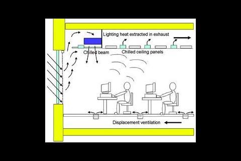
Another advantage of locating chilled beams in the building perimeter is that the plume of warm air rising from the window enhances the temperature difference seen by the chilled beam, and so raises its cooling performance without changing the size of the chilled beam or lowering the chilled water supply temperature. In some cases a second row of chilled beams is installed where the perimeter solar gains are too great for one row. Figure 1 shows a typical perimeter chilled beam scheme.
An additional advantage of perimeter chilled beams is that they minimise the disruptive effect that solar gains can have on air temperature and air circulation away from the perimeter. This is especially important where displacement ventilation and/or chilled ceilings are used Design issues
As perimeter chilled beams rely on the warm air plume from the window passing up to and through the device, their effectiveness will depend on where and how they are installed, and especially the interaction of the plume with building elements such as ceiling tiles and soffits.
A common factor that can adversely affect performance and thermal comfort in the perimeter zone, is the architectural/aesthetic requirements of commercial building designs. Architects and clients often expect a continuous suspended ceiling with uniform appearance and height right up to the facade. This can conflict with the requirement for unhindered air paths around the chilled beam and for effective capture of the thermal plumes from the window.
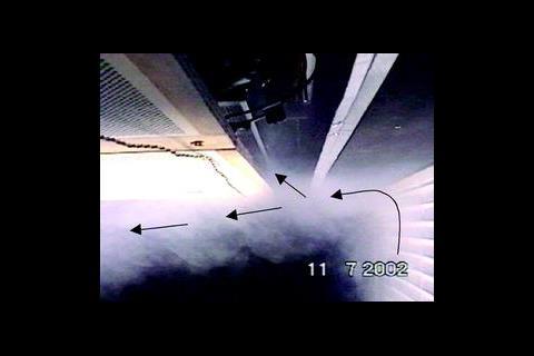
The building frame can also have a significant impact on perimeter chilled beam performance because its width determines how close the chilled beams can be to the top of the glazing, and how much space there is for a gap between the building frame and the chilled beam. These factors affect how well the thermal plume rising from the glass and window blind is captured by the chilled beam. Figure 2 shows smoke visualisation of the thermal plume with a wide framed building. With a wide framed building, there is often pressure from architects to minimise the width of the slot gap at the ceiling perimeter thatthatwhich forms the ceiling void entrance, as its position is beginning to intrude further into the interior ceiling area. Laboratory mock-up tests have shown that this causes a greater proportion of the thermal plume to miss the entrance to the ceiling void and continue moving across the underside of the ceiling.
The key to good design
There are a number of factors that can inluence the design of a good perimter chilled beam scheme including ceiling tile type. In some buildings the client and architect are happy for chilled beams to be visible to the room. But it is probably more common for a perforated suspended ceiling to be installed to obscure the beams and chilled water pipework, and present a flat overall surface. Unfortunately the perforated ceiling tiles will restrict air flow between the beams and the room, depending on the free area and actual hole dimensions.
If a suspended ceiling cannot be avoided it is important to select a tile with a high free hole area and a large hole size. It is recommended that louvred tiles, or tiles with a free area no less than 50% and hole size maximised (for example 10 mm diameter), are specified.
The effect of window blind type is a further consideration. Windows that are susceptible to solar gains are normally fitted with some form of shading or glare- control device. Where external shading is not provided, it is usual to provide either nenetian or roller blinds on the window's room side.
Slatted venetian blinds can also have an impact on the overall performance of the installation. Tests with a mocked-up horizontal slatted venetian blind have shown that when the slats are closed the thermal plume on the window side of the blind is physically constrained. When the slats are partially or fully open the plume can pass through, causing more rapid growth of the warm air plume on the room side. This has an important influence on how much of the plume enters the ceiling void and passes through the perimeter chilled beam, and therefore on the thermal comfort in the perimeter area of the room.
Tests with a roller blinds show that the plume is more constrained than with a closed slatted blind. When a roller blind is down there is usually a small (typically 19 mm) gap between the top of the blind and the underside of the building frame. This results in a narrow jet of hot air issuing from the space between the window and the blind, a significant proportion of which enters the ceiling void via the perimeter gap.
It is therefore recommended that a fabric roller blind is specified in preference to a horizontal slatted type. If a roller blind is used, it is important that the gap between the top of the blind and the underside of the building frame is minimised. If horizontal slatted blinds are specified then clear operating instructions and occupant buy-in is required if perimeter chilled beam performance is not to be compromised.
The heigh of the ceiling can also influence things. A significant factor in the performance of perimeter chilled beams is how well the thermal plumes from the window and blind are captured and fed to the chilled beams. The underside of the building frame at the top of the façade has a tendency to deflect the thermal plume past the perimeter slot gap and therefore miss the ceiling void. By lowering the ceiling and chilled beams relative to the building frame, the plume can be captured and fed into the ceiling void.
Further advice
Other design options, such as angling the beams or placing them perpendicular to the façade, were also found to improve cooling performance. All this information, together with detailed design advice for narrow, wide and shallow frame buildings, is included in a forthcoming BRE Information Paper, due to be published this summer, and available from www.brebookshop.com.
Source
Building Sustainable Design
Postscript
Acknowledgements: the information in this article is the result of a DTI Partners in Innovation project, led by BRE and supported by the Foundation for the Built Environment, Barrett Ceilings, CIBSE, Hoare Lea Consulting Engineers, Klima Therm and SAS International.


No comments yet