In this month’s engineering services cost model Davis Langdon Mott Green Wall examine the rationale for installing standby generators, and consider the technical, accommodation and cost implications of various performance options
Standby generation may be justified on two grounds: either life safety or because a building occupier considers that the supply availability from the distribution network operator is inadequate to support their business requirements.
In terms of life safety, BS 5588 recommends that any substation, distribution board or generator that supplies power to life safety installations, such as the fire-fighting lift, should be protected from the action of fire in the building for a period not less than that specified for the fire-fighting shaft. In practice, this means a form of construction with least two hours of fire resistance.
All safety services, such as sprinkler and fire fighting pumps, staircase pressurisation, smoke clearance equipment and emergency lighting, require standby power sources and circuits that are adequately fire resistant and independent of the primary supply. If the primary supply fails, as a result of fire damage or some other emergency condition, then the standby supply is required to be available and to change over automatically. The short break of supply (15 to 25 seconds), during which the standby generator starts and achieves suitable voltage and frequency conditions, is normally acceptable, except for emergency lighting which is battery-backed and changes over almost instantaneously.
Basic standby operation
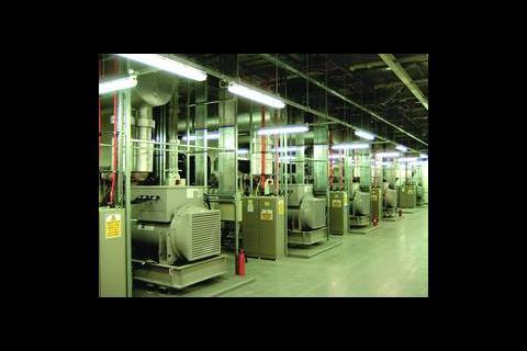
The vast majority of standby generators consist of an automatic start, water-cooled industrial diesel engine governed to run at 1500 rpm, close-coupled with a three-phase, 50 Hz, 400 V alternator and supplied with a control panel and exhaust system.
A mains monitoring device is normally connected to the live side of the incoming mains circuit breaker to detect when the mains supply voltage has failed or dipped to a preset level. This signal is transmitted to the control system to start the engine after a preset delay (normally 3 to 5 seconds). As soon as the alternator has settled to its correct voltage and frequency, the control system will initiate the supply change over by operating the alternator output circuit breaker or contactor. When the mains supply is restored, this event will be sensed by the mains monitor and after a short delay to ensure stability, the control system will initiate the changeover from generator to mains by switching off the generator and switching on the mains supply, before shutting down the generator. Figure 1 shows a typical control block diagram for a standby generator.
Synchronisation and paralleling
When the mains supply returns to normal, the changeover sequence from generator to mains can be achieved without a break if the generator output voltage and frequency can be closely matched to the mains supply. This synchronisation operation can be achieved reliably and automatically in a matter of seconds, and provided that the control and protection arrangement meets the supply authority G.59 engineering recommendations, then the load can be transferred back to the mains without another supply disturbance. The G.59 equipment ensures that rapid disconnection of the generator is achieved in the event of a mains supply failure while the two supplies are in parallel.
Synchronisation and paralleling facilities may also be specified when the load is so large that a single generator cannot be conveniently installed, or when additional resilience is required by means of an N + 1 system. Automatic synchronising and control systems can optimise the number of sets running to the prevailing load, and paralleled generators may also be paralleled with the mains, to achieve a no-break supply restoration. Although simple in concept, these facilities do add to the system cost and complexity and need to be exercised routinely to maintain confidence.
Generator set dimensioning
Standby generators are generally specified to have a nominal electrical capacity in kVA at least equal to the total load that has to be supported. There are limitations with regard to the amount of load that can be accepted in a single step (typically 50% to 60% of rated load). Over-sizing may be needed if the load comprises:
- Large induction motors (eg chiller machines)
- Large non-linear loads such as battery chargers or uninterruptible power supply systems.
Designers should be aware of these potential problems, and may specify load-shedding or timers, ensuring for example that the largest motor is connected first, to avoid unnecessary over-sizing of the generator system.
It should also be remembered that an electrical protection grading study, carried out for the mains supply, may not be adequate for the same installation supplied from a diesel generator, which has a much higher source impedance. For all of these reasons, the generator set manufacturer should be provided with as much information as possible about the nature of the intended load.
Accommodation issues
Except for the very largest generators, a load-bearing reinforced concrete floor is adequate to accept the normal arrangement of a fabricated steel bed plate with the engine alternator supported above on anti-vibration mountings. Architects often choose to locate generators in the dead space in basements, but this is far from ideal when considering heat rejection and ventilation. From an engineering viewpoint, a ground floor location with access to outside walls is favourite, and a roof-top installation can also be advantageous in terms of ventilation and exhaust arrangements.
Diesel engines are inherently noisy, producing typically 110dBA inside the engine room. High performance absorption type primary and secondary silencers, matched to the engine exhaust gas noise and flow rate, will normally deal with external noise issues. A further tertiary silencer may need to be mounted at the end of a long exhaust run.
Generator noise breakout may be reduced by lining the engine room walls with sound-absorbing material, and antivibration engine mounts will reduce transmittance to the building structure. Remote radiators can also assist by removing that source of noise to a more suitable location.
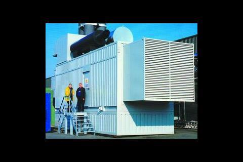
Airborne noise is a problem that may need to be solved by specifying splitter attenuators at both the inlet and outlet ventilation air apertures. These consist of a robust chamber with noise absorbent panels arranged in parallel with the airflow. Another possible approach, where the accommodation is suitable, is to enclose the generator set in an acoustic canopy or ISO container to achieve the required sound attenuation.
A large quantity of air is needed for engine aspiration and for cooling, to prevent excessive temperature rise within the plant room. Ventilation should be arranged ideally so that outside air is drawn from the alternator end, and then across the engine to remove radiated heat. In most installations, the engine-mounted radiator fan will push air through the radiator matrix, via a short section of flexible ducting into the discharge attenuator, to outside. Care must be taken to separate the room inlet and outlet apertures to prevent the possibility of recirculation, and consideration must also be given to the possible effects of prevailing wind. These ventilation requirements can be very difficult and costly to implement, especially to basement engine rooms. Mounting the engine radiators remotely may help, but then additional fans will be needed in the engine room to provide an adequate air flow.
Life safety generators are normally specified to run for at least three hours and larger sets will require bulk fuel storage; local regulations should be checked to ensure that the storage arrangements are approved.
Most standby sets will have a daily service tank placed near to the engine and a bulk storage tank outside or separated from the engine room. If the storage or the fuel lines are exposed to low temperatures then trace heating should be installed to prevent waxing, which could result in blocked filters and system failure. Fuel oil tank capacity is often specified as a number of hours running at a stated load, and a good estimate may be based on 0.25 litres of fuel per kilowatt hour at rated load.
Diesel fuel stores in excess of 450 litres may be considered as areas of special fire risk. Local authorities may require them to be located at or near ground floor level, near an external wall, and separated from the rest of the building by construction with a four-hour standard of fire resistance, and with two-hour doors that are either self-closing or kept locked shut when not in use. Ventilation to open air will be required to prevent stagnation. Some form of effective bund to contain a spill or leakage will also be required, normally supplemented by floor-mounted electronic leak detection. External fuel storage is subject to the Control of Pollution (Oil Storage) (England) Regulations 2001.
A free-fall (gravity operated) fire shut off valve will be required to cut off the fuel flow from the storage tank. This may be tripped by a temperature-fusible link in a strained wire and pulley system, or by a sensor switch, mounted above the engine.
- Acknowledgements; Davis Langdon Mott Green Wall would like to thank Broadcrown for its assistance in the preparation of this article.
Downloads
FIGURE 1: Control block diagram for a standby generator.
Other, Size 0 kb
Source
Building Sustainable Design


No comments yet