


Designing and installing the services on Europe’s biggest construction project is no easy task, but Amec claims it can do it six months early with half the usual site labour. In the first of two special T5 features, we reveal the services contractor’s secret weapon …
Parabat Garga is under no illusions about the scale of the task his company faces. As project director for Amec Services, he is responsible for the detailed design, procurement, installation and commissioning of the mechanical services for a large part of BAA’s Heathrow Terminal 5 project. “It is one of the largest M&E installations ever undertaken by a UK contractor,” he says.
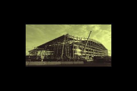
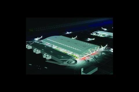
The £4.2bn terminal under construction in west London is said to be the biggest construction project in Europe. It includes a 396 m long, 176 m wide, 40 m high glass-clad main terminal building; a 442 m × 52 m satellite terminal (itself bigger than Terminal 4); a 4000-space multistorey car park and tunnel extensions; and a new station for the Heathrow Express and the Tube’s Piccadilly Line (see site plan below). All this construction is taking place between two of the world’s busiest runways, with planes taking off and landing every 90 seconds. If you add to this the challenge of getting men and materials to the site through a single access gate, time constraints on delivery vehicles on the nearby M25 and an immovable construction programme, you can see just why the scheme is such a challenge.
Despite the gargantuan nature of the project and the tricky site constraints, Garga is making some astounding claims. He says the contractor will undertake its share of the £600m of services work with less than half the site labour that would conventionally be required. Not only that, but he insists Amec will actually “cut six months from the project’s original build programme”.
Garga can only make these impressive declarations because Amec has decided to make extensive use of off-site manufacturing techniques. Prefabrication of a building’s services is not new; pre-assembly has been used on a variety of buildings, including London’s Tower 42 and Birmingham’s National Exhibition Centre. However, the challenge for Garga and his team is to prove that modularisation can work on such a complex project.
Sitting in the design office dressed in a tweed jacket, Garga looks more the academic than construction revolutionary. It is when he talks construction, however, that his radical principles come to the fore. “The conventional approach is to erect 80% or more of the M&E services on site, which is a laborious and time-consuming activity; on this site, however, Amec is assembling over 60% of the services off site,” he explains. In addition to increasing productivity, Garga says that this approach is superior in other areas: “Assembling the services in a factory is safer for the operatives; their workspace is cleaner and consequently the quality of their work is better; there are fewer men on site; and there are fewer materials to be delivered to and stored on site”.
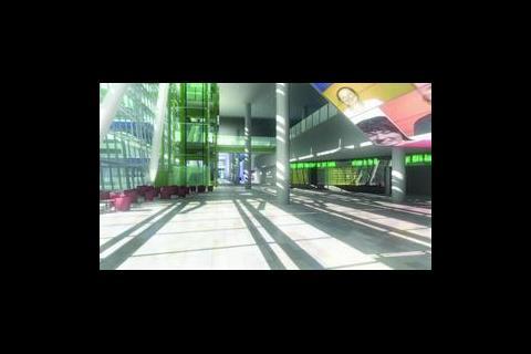
On site, the main terminal’s roof is almost complete. Architect Richard Rogers Partnership’s design features a huge wave-form roof supported on a series of X-shaped tubular steel abutments. The building’s fully-glazed facades appear to hang from this roof like glass curtains. Rogers designed the roof and facade structure to be completely independent of anything inside the terminal; this gives BAA great flexibility for the future and, more importantly, it allowed construction of the building’s shell to commence while the layout of the interior was still being finalised.
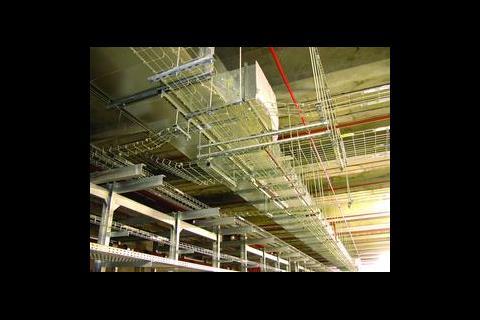
Consulting engineer DSSR developed the concept design for the terminal’s services in partnership with fellow consultants Mott MacDonald and Parsons Brinkerhoff. The basic plan is to take the main services – electric power, heating and chilled water – from a separate energy centre to the south of the main terminal building, pipe them through underground tunnels into the basement of the new terminal and its satellite, and then direct them through the terminal’s basement to 11 key riser points within the terminal itself. In addition to the pipework, these risers will also house ventilation plant, IT rooms and staircases.
The consultants opted to use a constant volume air displacement system to keep conditions inside the terminal comfortable. This works by drawing fresh air into the terminal through an enormous builderswork duct in the terminal’s basement, where it is filtered and heated before being ducted to the base of each of the 11 risers. These risers are, in effect, a series of five plantrooms stacked one on top of the other; one air-handling plantroom for each of the building’s five main floors – 55 plantrooms in total. The fresh air is supplied to each air handling unit, with exhaust air expelled through eight chimneys mounted on the terminal’s roof.
The initial concept from the consultants was handed over to services contractors to design and install. The consultants then have a watching brief as “concept guardians” according to Garga. Along with Amec, other services contractors working on the scheme include Crown House Engineering, on the £350m satellite terminal, and Balfour Kilpatrick, on an £80m services contract for a railway station and tunnels.
We’ve modularised all the primary distribution pipework on a scale never seen before in the UK
Jim Hutchison, services project leader, Amec
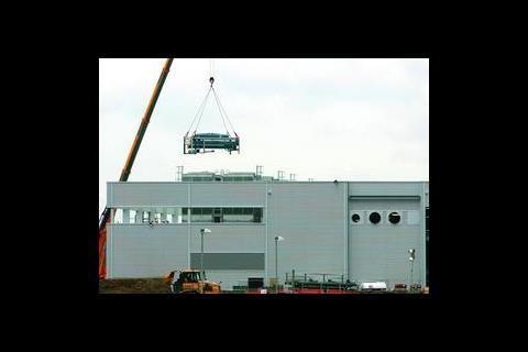
Amec developed a modular system for the off-site manufacture of services for the main terminal building and its energy centre. Each module consists of a rectangular steel frame into which all the service pipes, ducts, electrical cable trays and even some of the plant are installed. Groups of these modules will be pre-assembled in the fabricator’s yard before being delivered to site to ensure they fit together and to enable some systems to be commissioned before leaving the site. “The modules are small enough to fit on the back of a lorry,” says Garga. More than 5000 modules based on 11 standard module types will be supplied to the main terminal building alone.
Jim Hutchison, Amec’s services project leader, starts his tour of the project at the terminal’s energy centre. This grey, industrial shed houses 43 MW of heating and 27 MW of cooling plant for the main terminal building and its satellite. In the future it will also be home to the plant for a second satellite building, to be constructed under the scheme’s second phase.
Stepping into the energy centre, the first thing to catch your eye is a line of four giant chillers lining the north wall. The size of each 6.6 MW chiller meant it had to be delivered in three sections, jacked into position and then assembled. BAA’s specification for an energy-efficient, environmentally friendly cooling systems means all the chillers use ammonia as a refrigerant. The chillers are in the process of being connected to eight roof-mounted wet cooling towers, with their pipework modules craned into position on the roof.
At the eastern end of the energy centre is the terminal’s heating plant. Two enormous cylindrical boilers, their burners still sheathed in polyethylene wrapping, lie on skids waiting to be moved into their final position. Once Amec receives delivery of a smaller third boiler, all three can finally be manoeuvred into place.
High overhead the building’s ceiling is a maze of pipework and ductwork. “We’ve modularised all the primary distribution pipework in the energy centre on a scale never seen before in the UK,” Hutchison says. The modules were installed in what Hutchison describes as “trains”. Each train comprises 10 modules bolted together on the ground. The modules house all the pipework and ductwork and cable trays and even come complete with sections of the energy centre’s mezzanine floor. The 10 modules are lifted as a complete assembly in a single 100-tonne lift using strand jacks. “The advantage is you are lifting the floor up with the pipework so that you don’t have men working at height,” Hutchison explains. “And once the modules are installed you can work underneath them immediately,” he adds.
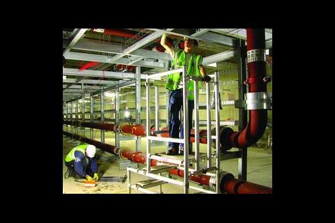
From the energy centre, heating and cooling pipework snakes to the main terminal and its satellite through 1.5 km of tunnels. Outside the energy centre, a scaffolding lid covers the hole where pipework modules were lowered into the underground ducts. In addition to the 600 mm diameter cooling pipework, the tunnel modules contain heating, cold water, drinking water and sprinkler pipework. “The distances involved lend themselves to modularisation,” says Hutchison. The project’s phasing means that there is still one leg of pipework still to be installed before it can be cleaned and flushed.
Beneath the main terminal, the heating and cooling mains split to serve three subterranean “wet” plantrooms. From here the mains branch out to feed the base of each of the 11 service risers. Currently Amec has installed about 60% of the pipework in the building’s basement.
On the terminal’s ground floor, or apron level as it is known in airport parlance, the first modules to form the service risers are being installed, beneath the terminal’s giant roof. A mezzanine floor partially fills the space beneath the roof, within which 11 huge voids rising up to the roof mark the positions where the service risers have yet to be installed.
We’re aiming to have 70%of the building’s services prefabricated by the end of the project
Parabat Garga, project director, Amec
Work on Riser S1 is the most advanced, with the top two plantroom levels already in place close to the roof’s underside. At the moment a team of five men from a specialist lifting company are grappling with the four modules that will form the riser’s basement plantroom. Each module was delivered to site on the back of a truck. A specially constructed gantry then lifted the module clear of the vehicle before placing it on a motorised bogy. Inside the terminal, the module is transferred from the bogy to a lifting frame. Once all four modules are in place and have been bolted together, the competed assembly will be lowered into position using four strand jacks. Four outriggers will support the plantroom from the floor slab to allow the lifting frame to be removed.
Amec is using two fabrication companies to assemble the modules. Babcock Engineering Services, in Rosyth, Scotland, will put together the more complex core modules, while Kent-based WS Britland will assemble the pipework distribution modules. Wisely, Amec involved the fabricators in the design of the modules to speed production. “If you design the modules to suit the manufacturing facility you will get a more cost-effective design,” Garga explains.
Before construction started in earnest, a series of sample modules were constructed. This allowed the fabricators to establish an assembly methodology and enabled the designers and erectors to review the module’s construction and set a workmanship benchmark for subsequent modules.
Using fabricators based in other parts of the country has other advantages for the T5 site. Garga says that having the modules manufactured off-site helps ensure there is a workforce available to put them together, while reducing the demand on skilled workers on site. The modules will be delivered to site directly from the fabricators as they are needed. “If we need to make an adjustment to programme, we can stockpile the modules off-site,” he says.
However, Amec has not modularised everything. The pipework has been delivered in modules, but it is delivered without insulation. According to Garga it is more cost effective to apply insulation in long lengths, preferably later in the project when the possibility of damage has diminished. And, although the cable trays are part of the modules, cabling contractor EDF will not roll out the power cables until later in the programme. “It is uneconomic to lay the cables as modules,” Garga says.
One of prefabrication’s benefits is that it is compatible with state-of-the-art design systems. Before the modules are assembled, their virtual, digital forms are inserted into the T5 single project model (see page 29), which allows Amec to eliminate several nightmare scenarios in advance. In addition to detecting any clashes, the model allows what Garga describes as “construction studies” to take place: this is where the service modules are put together into runs and risers to work out the most efficient way of assembling them.
Amec has also involved BAA’s facilities managers in the design of the system in what Garga calls “front to back engineering”. He says: “We wanted to ensure the services are efficient to run and maintain so we involved people that will operate the plant throughout its life.” The single project model allows BAA’s facilities management team to “walk through” the building to check for access problems when servicing the plant. Once everybody is satisfied, the 3D CAD models are transferred directly to the fabricators for construction. “We realised we needed to plan our process in a different way. We did it through web-based technology to plan the logistics, manufacturing data and materials flow,” explains Garga.
With 60% of the building’s services prefabricated, you would have thought Garga would be satisfied. Not a bit of it: “We’re aiming to raise that figure to 70% by the time we near the end of the project,” he says. The first modules to form the terminal’s risers are starting to be installed – the pressure is now on Garga to prove his claims if the terminal is to open as scheduled on 30 March 2008.
T5 facts
- Terminal 5 is the largest construction project in Europe
- The new terminal will handle 30 million passengers a year
- The terminal will cost a total of £4.2bn
- At 400 m × 150 m, the main terminal will be one of the largest single-span structures in the UK
- The building will have 175 lifts and 131 escalators
- There are more than 13.5 km of bored tunnel – equivalent to about a third of the underwater section of the Channel Tunnel
- The area of the T5 site is 260 ha, or about the size of London’s Hyde Park
- There are more than 6 km of site roads
- More than 100 ha of the site were excavated and surveyed by the archaeologists
- Every day 260 vehicles an hour pass through the site entrance
- By the time the project has been completed 6.5 million tonnes of earth will have been moved
- The aircraft stands will cover an area equivalent to 120 football pitches
- At its peak there will be 5000 workers and 2000 support staff on site
- If will take 37 million man-hours to build T5
- There are 16 canteens on site serving 22,000 meals each week
Single project model

Part of BAA’s strategy for getting Terminal 5 delivered on time and to budget is a common 3D computer model, called the single project model. Post mortems on some of the airport operator’s previous projects showed that many went over budget because of inconsistencies with drawings. BRE and BSRIA have estimated that up to 30% of the construction cost of a building is wasted during its development and delivery.
Mervyn Richards, CAD technology manager for main contractor Laing O’Rourke, says that on a large project there may be many changes, so when the contractors get to site they are all working from slightly different information. This means that sooner or later they end up with the wrong thing in the wrong place; time is then spent putting things right, adding to the programme and increasing costs.
More than 120 consultants and specialists are working on T5, generating thousands of drawings, so there could have been a massive potential for errors to creep in. However, by using a single project model, based on Autodesk’s architectural desktop software and enhanced by software developed by Excitech, only one set of data is used by everybody. This approach drives out errors and improves efficiency, as well as saving on drawing production costs.
The single model environment also incorporates intelligent object technology for greater efficiency. This means that objects in the model possess information about themselves and how they relate to other objects in the building.
Information from the model has been used in the construction of the terminal’s substructure and superstructure. And because the model is constantly updated with as-built information, such as small variations on site, it can be used with absolute certainty.
In addition to design information from the consultants, this common data contains information from fabricators, manufacturers, contractors and installers. It also includes cost information, lifecycle costs and construction planning. And when construction is complete, the model will even help the airport operator maintain its buildings by linking it to the facilities management systems. This will be useful if, for example, a series of valves keep failing as it will be possible to change their specification on the next project. The facilities management teams and others without specialised CAD skills or software can see the information in the model using a 3D viewer called Navisworks.
The challenge with using a single object model is that it needs discipline to make it work. Everybody must follow the same rules and conventions when inputting information to ensure the CAD data is dimensionally correct. However, the benefits of this approach are expected to be enormous, enabling BAA to cut the cost of its building procurement by up to 10%. And the rest of construction will also benefit from BAA’s work: lessons learned at T5 are being fed into a DTI-funded project called Avanti, whose aim is to show how smaller projects can benefit from the single model environment.
Terminal 5 timeline
August 1989
Project starts; architect Richard Rogers Partnership wins the competition to design the terminal
February 1993
Planning application submitted
May 1995
Planning application is put to a public inquiry
March 1999
Public inquiry ends
November 2001
Planning approval granted – subject to more than 700 conditions
May 2002
Legal challenge to approval dismissed by the High Court
July 2002
Site preparation begins, including an archeological dig and construction of the site facilities
September 2002 Official start on site; excavation and construction of the basement of the main terminal and its satellite
February 2003 Planning permission granted for the final terminal building design
November 2003 Work begins on construction of the building’s superstructure
June 2005
Topping out ceremony for the main terminal building
January 2007 Scheduled handover of the terminal to BAA; start of system testing
30 March 2008 Terminal 5 opens to the public
Systems integration

The most critical activity to get right if the new terminal is to open on time is integration of the buildings services, security, fire and lighting systems. Get it right and the public’s experience of the terminal will be a positive one; get it wrong and the terminal’s opening could be horribly delayed.
Integration is complex. It means that if a fire alarm goes off in one part of the building, all the doors to the runway and secure areas don’t fly open automatically. It also includes the flow of information between air-traffic control in Swanwick and the airport, the updating of flight information, the baggage handling systems and the organisation of aircraft gates and stands.
BAA has opted for a low-risk strategy at Terminal 5. It is aiming to do the bare minimum to get the terminal functioning safely on the first day. It will then gradually introduce more complex integration over time after the building has opened. This has two advantages: first it means that the latest software can be used as it becomes available; second, the integration will reflect the changes in the building’s use over time.
Initially, tried and tested off-the-shelf systems will be used. For example, the building services manufacturers’ own interfaces will be used. However, BAA will tie these together using a massive building management systems interface to make it easier for operators to control the building and for the engineers to commission the terminal to ensure it opens on time.
The satellite terminal

Were it not for its big brother, the £350m satellite terminal would be the star of T5. On its own, this terminal is bigger than the airport’s Terminal 4. It will also provide the only aircraft stands on T5 capable of receiving the Airbus A380 “superjumbo”, as well as acting as the main baggage hub for British Airways.
Construction of the 52 m × 442 m satellite is well under way and in many ways mirrors that of the main terminal building: its four superstructure levels are topped with a single-span waveform roof structure supported from steel trees and the services for this building to are being manufactured off site as modular units. On this building, however, the M&E contractor is Crown House Engineering. A second similar satellite is planned for construction under phase two of the project but this is not due to start until 2006.
Servicing the infrastructure
Balfour Kilpatrick is installing the M&E services at Terminal 5. Working in a 50:50 joint venture with Balfour Beatty Rail Projects, the company has completed the design of the M&E services for London Underground’s Piccadilly Line extension and the Heathrow Express extension, with installation due to commence next month. The firm is also about to start installation of the £27m services contract for T5’s railway station, and the £16m M&E fit-out of the stations for the automated people mover to ferry passengers between the main terminal and the satellite.
Balfour Kilpatrick has also used modularisation. For the station, the contractor has developed a lighting, public address and fire service module, which will be installed above the platforms. One innovative development is that the station’s lighting system will make extensive use of mirrors and spotlights to bounce light around the building: this allows the lamps to be fixed where they are easy to access for maintenance.
Downloads
The Terminal 5 construction site: what’s happened so far
Other, Size 0 kb
Source
Building Sustainable Design

No comments yet