


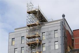


Considering that the majority of TT installations in the UK are installed in domestic and small commercial premises, most often in rural locations, it is often left to the smaller electrical contractor to take a view on the likely increase in resistance of installed earth electrodes.
There are some basic trends that apply to the majority of these electrode installations in the UK, and this article attempts to give some guidance on the subject.
It should be noted that a specialist subcontractor should undertake the designs of low impedance earthing schemes and those on rock and very sandy soils. Such schemes are outside of the scope of this article.
Despite reference to a maximum resistance of 220 V, mentioned in the IEE On Site Guide, a maximum resistance of 1666 V with a 30 mA rcd can be installed if the value is unlikely to increase in the installation life.
However, to take advantage of this rather high value, it should be appreciated that the electrode depth is the likely factor when investigating increases in electrode resistance.
Detrimental conditions
Frost and dryness are the two main enemies responsible for increased resistance. A 2 m or 3 m rod electrode with an initial reading of 350 V will generally be considerably more stable to seasonal changes than a 1 m rod with an initial reading of say 220 V.
This is due to the fact that seasonal changes, including frost and dryness, will obviously have more effect on the superficial soil (or top soil) layer.
Let's now consider the effect of frost and dryness on some typical vertical rod electrodes in the UK.
BS 7430 suggests that the first metre of an earth electrode should be discounted due to possible frost and dryness interference and the associated severe drop in soil resistivity. This is fine for low resistance schemes but is not quite so relevant for schemes for 100 V or so.
Even with a frost of -5 degrees C to a depth of 1 m, the top metre of a rod-type earth electrode will still 'contribute' somewhere in the region of 700 V to the overall resistance value. Typically, therefore, a 2 m rod with an average installed resistance of 150 V would only increase to about 250 V if the top metre were in frost conditions.
For dryness conditions, BS 7430 gives soil resistivities based upon a low rainfall of 250 mm per year (ie desert conditions). Similarly, the top metre of a rod electrode in these conditions will still 'contribute' and provide some earth resistance.
For most soil types a 2 m rod will have a typical resistance to earth of about 25 V. Even under a rainfall of 250 mm per annum the resistance of most of this rod electrode would not increase to more than 100 V.
It can be seen that, for rod earth electrodes, the top metre will contribute to the value of resistance required in a TT installation in both frost and desert conditions.
Testing
The soil conditions at the time of installation of the earth electrode shall be considered prior to carrying out earth resistance testing. If the rod is tested at the end of a month without rain this should be noted for comparison with table 1.
These values should be used for average soils and locations (excepting sand, slates and rocks) as maximum values at installation of single vertical rod earth electrodes.
In conclusion, a single earth rod electrode in a TT installation is a critical link in providing the protective measure against indirect contact by the automatic disconnection of supply method.
It should be recognised that the values given by Regulation 413-02-20 in BS 7671 should not be exceeded and that in this respect the depth of the electrode is the critical factor in any installation. A 2 m depth electrode should be considered minimum and one of 3 m is preferred.
Source
Electrical and Mechanical Contractor
Postscript
Darrell Locke is technical manager at the ECA.
