


The architect behind the retrofit of an Edward property using Passivhaus principles takes us through the strategy for achieving airtightness…
Our original energy calculations for the house before works commenced indicated that loss of energy through uncontrolled air leakage represented about one third of the total heat loss. As one adds insulation conductive heat losses drop dramatically, but if airtightness is not addressed specifically then there is still a potentially large loss remaining.
Of course the insulation linings are likely to help control air leakage to some extent but experience shows that even modest gaps and cracks left during ’normal’ building works only reduce this energy path by about half. In order to reach our target of reducing heat loss by a factor of 10, we need to do vastly better than that. Previous experience by our team and others shows that even on refurbishment achieving very good results can be achieved if the following issues are born in mind during design and carried through on site:
- Strategy – have a clear strategy for the whole house. Make it simple to understand and build. Any confusion or requirement for origami type skills will lead to failure.
- Name the air tightness layer explicitly - while all the layers in any construction may help, it is important that one layer is named and made continuous. One bucket without any holes is always better than one leaky bucket inside another leaky bucket.
- Continuity - maintaining absolute continuity of the air tightness layer is essential. Any compromise or design fudge in this is likely to cause major problems.
- Junctions - every time there is a geometric junction between say a wall and a ceiling or a material junction say between oriented strand board and a plastered wall, there is a potential weak spot. There are now available a range of tapes which can solve most of these problems, so ensure the team know which one they are using where and that it available on site when needed. However, the tapes are a tool and not a solve all magic bullet. Designers should give special care to how each junction will be made and the sequence that should be followed. Avoid complex geometries and consider whether someone can physically carry the work out on site. Tapes can be fitted to single curved surfaces but double curvature makes for difficult messy work that is likely to fail.
- Penetrations - all penetrations (incoming and outgoing services) though the air tightness layer must be managed carefully. Special grommets and sleeves produced by the same companies that make the tapes are available. Again make sure they are on site at the right time. As with junctions consider carefully how the penetration will be made on site and make the geometry simple.
- Rules on site - everybody that comes over the threshold on site should be made aware of the importance of the air tightness strategy. Trades that join the build later in the process and carry hole making tools, such as electricians and plumbers need to understand the importance air tightness and how it will relate to their work.
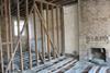
The air tightness layer in our project is either a wet plaster layer or a dry oriented strand board (OSB) layer. Generally the ceilings are all formed using OSB within the insulation build up.
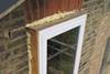
The front wall, party walls and suspended ground floor are also sheathed with OSB (or particle board) as an air tightness layer over the insulation layers. Every joint between the OSB sheathing is taped. Corner junctions can be done fairly easily with this dry form of construction. We are using a tape which is both very sticky and can accommodate a little movement. All window frames will sit within plywood boxes that can be taped to the internal sheathing and thereby provide continuity to the window frame.
The walls to the back of the building which will be insulated externally have an internal air tightness layer formed with a wet finish - two coats of sand and cement with a skim finish. This finish will extend through the joist zone at first floor and down to the ground floor slab. To make connections between this wet layer and the dry OSB ceiling or plywood window boxes, we are using Contega tape by Pro Clima. This tape has a layer of polyethene film coated in a fluffy felt like outer layer. One edge has sticky side when the release tape is removed allowing it to be fixed to the dry sheathing layer. The other edge can be bonded into the first coat of sand and cement with a mastic glue know as Orcon F that is supplied in cartridges and gunned on (very sticky stuff). When the Orcon has cured another coat of the render can be applied over the fluffy tape. The tape is then mechanical and chemically bonded into the air tightness layer.
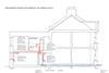
This strategy has enabled us to create a continuous air tight layer using two commonly available materials (OSB and render) and two types of tape. Almost all conditions can be dealt with in this manner. Consistency of detailing lessens the burden on the site team and allows them to refine their technique. We have reduced the number of penetration of the envelope as much as possible. No internal eclectic runs or back boxes penetrate the air tightness layer. Instead all services run either in the joist zone at first floor, the internal stud walls or service voids formed between plasterboard battened off from the OSB layer. 12 special grommets or sleeves will be used for all of these unavoidable penetrations.
2 for soil vent pipe (through slab and through ceiling)
1 for pressure release pipe from boiler/thermal store
3 for mains supplies (gas, water, electricity)
2 for MVHR pipes (inlet and outlet)
1 for feed from photo-voltaic array on roof
4 for communication (BT, cable TV and 2 spare)
We hope to be done with the air tightness works and most of the insulation within a few weeks, with a view to conducting the first test in early August.


No comments yet