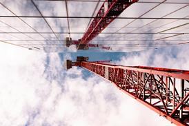
Fine steel rods, suspended from a series of slender masts evenly spaced along the 135 m clear span, support the bridge’s linear deck high above the dock. Two thin, raked, trestle legs transfer the structure’s weight to the ground. At each end, where the deck extends beyond the main supporting masts, narrow tie-down rods anchor the structure to the ground.
The bridge was to have been the first transporter bridge to open in Britain since the turn of the century. In the original scheme, passengers would have stepped from the dockside into the covered cable-car suspended beneath the bridge’s single high-level deck that would have transported them to the far side.
The bridge’s visual impact is stunning, but its primary design feature, the cable-car, has been omitted. Instead, pedestrians will be forced to cross the bridge, exposed to the wind, via its high-level deck, which is accessible only by lift or stairs. Without the cable-car, the whole design rationale comes into question.
Lifschutz Davidson’s design was the winning scheme of a competition run by the London Docklands Development Corporation in 1995 to find an alternative solution to a lifting bridge that allowed the dock’s continued use by the local sailing club, but which was covered to protect pedestrians from the elements.
High-level viewing platform
By providing a covered transportation cradle and suspending it from a high-level deck, both these requirements were met. The deck from which the cable-car was suspended also created a magnificent viewing platform from which to observe activities on the dock. The cradle would have provided a secure environment for passengers crossing the river in one of London’s less salubrious areas.
But the LDDC, worried that the legacy of maintenance and operational costs would have proved too expensive, decided instead to upgrade the bridge’s specification for pedestrians crossing its exposed deck. This involved increasing the number of access lifts to the high-level deck from one to two at each end, and adding a rain shelter at each end of the deck for passengers awaiting lifts.
The bridge was originally planned to open in spring 1998, but access problems on the northern approach have put this back to late summer 1999. The crossing was built to provide a pedestrian link from the new West Silvertown Urban Village on the south bank of the dock, to Custom House Station on the Docklands Light Railway on the north bank. Ultimately, the scheme will form part of a grand plan to open a route from the DLR station to the Thames Barrier through a series of new developments.
Looking down the dock, the bridge is strangely off-centre, set further into the south bank than the north. David Carr, project director with English Partnerships, which inherited the bridge and adjacent development schemes following the LDDC’s demise, says the lack of symmetry “is because a planned exhibition centre will project into the dock from its north bank”. Unfortunately, the latest scheme for the exhibition centre projects only 25 m into the dock, rather than the 50 m originally planned. An extended low-level pedestrian link will be required to link the bank with the scheme.
Ease of construction
Techniker designed the bridge’s structure with ease of construction in mind. A series of six braced isosceles triangles, formed from the masts and steel supporting rods and known as Fink Trusses, supports the five deck sections. This means of support had the advantage that, under construction, the bridge was virtually self-supporting and needed little temporary propping. Rods set in the ground at each end of the deck tie down the structure.
The ends of the bridge were constructed simultaneously. Piles were installed at each side of the dock for the trestle legs to sit on. A steelwork section, known as the cross-head, was then placed across each pair of trestle legs. The two end sections were then craned into place from boats and secured to the cross-head using a socket and spigot joint while the deck was supported temporarily from a barge moored in the dock.
Only after the landward-projecting sections of the deck had been attached to the same cross-heads could the two main supporting masts and their associated steel rods be fitted. The next two deck sections were then craned into place from the barge and their associated supporting masts and rods added before the centre section completed the deck. Once all the deck sections were in place, the tension in the steel supporting rods was adjusted using a mix of hydraulic jacks and turn buckles.
All the necessary equipment has been incorporated into the bridge’s design for the cable-car’s installation, if a developer ever comes up with the money for one. This includes rails for the car to run on, currently used by the bridge’s maintenance trolley, and housing for its power source. “Obviously we are disappointed,” says Lifschutz Davidson’s Charles Borthwick. “The concept was clever and it would have been an asset for the area.”
Credits
architect Lifschutz Davidson structural engineer Techniker quantity surveyor Davis a& Everest main contractor Kier London steelwork fabricator and erector Kent Structural Marine


