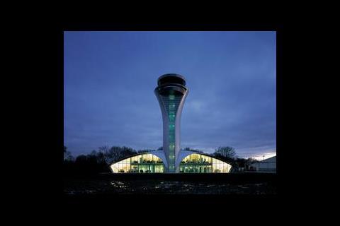
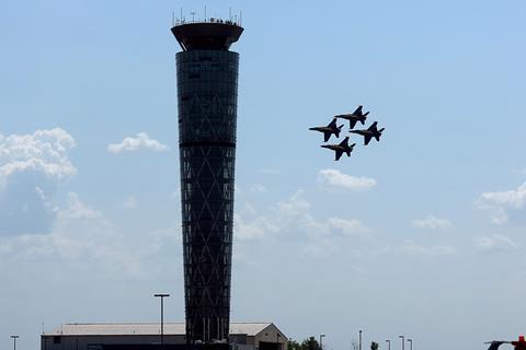
Following an architectural competition, Reid Architecture was selected for its elegant sculptural solution with complementing designs for the hangar and terminal buildings. "The building is architecturally led rather than just being functional," explains Brian Johnson, associate with Buro Happold who acted as both services and structural consultants on the scheme. "The early design concepts for the tower involved making a statement, with a tall, sleek and elegant structure being a prominent feature across the airfield,"
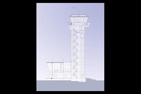
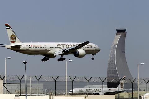
The 34 m tower sits just inside the fully glazed south elevation of a two-storey base building. The tower's stalk is constructed from a 4 m diameter slip formed concrete shaft which houses the lift, stair core and risers serving the visual control room (vcr) perched on top. The vcr is the most prominent of the three key areas within the building and provides panoramic views across the airfield for air traffic controllers dealing with take-offs, landings and ground movement of aircraft. A secondary steel frame fixed to the concrete shaft supports the tower's aluminium cladding, running from the vcr down to a 'cloak' section that merges into the base building's curved Kalzip standing seam roof.
The other key operational areas are located on the ground floor of the base building. These are the approach control room (acr) which houses up to five controllers coordinating aircraft within a given radius of the airfield, and the main equipment room accommodating navigation and communication systems and controls for the airfield equipment. Also wrapped around the central atrium on the ground floor is a rest room, kitchenette, locker facilities, workshop and briefing space, while at first floor level overlooking the main airfield are six staff offices, with a conference room sandwiched between the electrical and mechanical plantrooms along the rear elevation.
Servicing strategy
Buro Happold started detail design in early 2001 with work beginning on site in September of the same year. The project was tendered on a two-stage process and followed a tight schedule to meet the December 2002 deadline. "There was a cut off date when the MoD were going to stop operating the airfield and it had to be licensed by the CAA when responsibility of the airfield was transferred to TAG," explains Johnson.
The National Air Traffic Service (NATS), TAG's air traffic control contractor, provided generic design specifications for the various areas within the air traffic control tower, such as temperature and humidity levels and lighting requirements, and were involved throughout the briefing process. However, given that Farnborough isn't a public passenger airport, there was an element of flexibility on the specific requirements set out in these standard briefing documents and the requirements of the client. "Through discussions with NATS we were able to identify areas where we could adapt that specification slightly to particular parts of the building and its operation," says Johnson. "For example, the provision of dehumidification in both the acr and vcr."
A large factor for the building design and layout was the provision and routing of the primary mechanical and electrical services, with duplicate supplies and routes required on many of the systems to prevent operations being compromised by plant failure or maintenance.
Early design sketches reveal a much deeper base building housing larger plantrooms. However as the scheme was refined the decision was taken to reduce the bulk of the base building and it was agreed that the larger items of plant would be housed in an external compound in the carpark.
A large service trench carries the lv electrical supplies and pipework runs across the car park, entering the base building via two diverse routes before being distributed to the plantrooms. In terms of cable management a minimum of two independent routes had to be provided from the ground floor equipment room to the electrical risers, with a one-hour fire partition or a minimum separation of 6 m. The mechanical and electrical risers linking the plant and equipment rooms with the vcr conveniently sit either side of the tower's stair/lift core, which provides the necessary segregation. There are two riser spaces but effectively four risers, two for the general mechanical and electrical, and two for the NATS cabling distribution.
A small equipment room at the top of the stalk houses distribution boards which takes the electrical services and splits them before they enter the vcr. "The requirements are relaxed slightly as they come out of the top of these risers because we're going into a relatively small area," says Johnson. "It is very difficult to get those same levels of separation as there isn't the space and this was part of the detailed discussions we had with NATS."
The selection of the hvac system was influenced by a number of factors, notably the lack of space for large ductwork risers in the stem of the tower, low noise and maintenance criteria, and an avoidance of water based systems. As most of the operational equipment was procured through NATS, detailed information on equipment loads and heat gains was available. These showed reasonably low internal gains, with the most demanding period being during the Farnborough Airshow, which takes place every two years and as a rule is the only time when both the vcr and acr are fully staffed. Reid Architecture's bid to maintain the slender proportions of the tower meant an all air system was rejected due to the large plant areas which would be required and the large area ducts to be run in duplicate to the top of the tower. Close controlled ahus mounted locally required too much critical space in the working areas and central fresh air distribution with local extract needed duplicate ducts, but moreover meant that dumping the extract air straight outside would forfeit the ability to recirculate the extract air.
The design team settled on a fan coil system using a central heat pump unit for heating and cooling. "Although this solution introduced refrigerant and condensate pipework into the building, it was felt that by complying with the stringent routing requirements, the possibility of equipment failure caused by leakage could be mitigated by the reduced size of the service routes and risers," says Johnson.
The condenser units for the Mitsubishi City Multi vrf system are installed in the external compound and feed fan coils in the vcr, acr and equipment room, with radiators providing heating to the circulation areas. Pipework runs are long, around 85 m to the vcr, and care was taken in the routing of these to ensure that joints didn't occur in inaccessible areas, helping to minimise the potential for leaks.
Ducted fresh air comes from two air handling units located in the first floor mechanical plant room. "We derived the supply and extract routes to the operational areas first," says Johnson. "Other areas follow more convoluted routes to fit in with the building's architectural layout." For the acr and equipment room there is a degree of recirculation, however for the vcr stale air is extracted locally at high level. "This is purely because ducting it to the top and back down again outweighs any financial benefit," says Johnson.
Power supply
The electrical supply for the key areas is filtered through two ups systems, backed-up by a 380 kVA standby generator. Rather than having a parallel redundant system the loads are distributed evenly between the two uninterruptible supplies, so in the event of a break in either supply operations can run on the remaining half of the system.
As part of the base build, frames mounted at the end of the six equipment rack runs in the main equipment room support circuit distribution panels fed from the two ups systems and the back-up generator supply. The client, in conjunction with NATS, then determined what equipment was fed from the boards.
In addition to the back-up generator there is a portable generator connection point linked directly to the incoming switch panel. Johnson explains this is relatively inexpensive addition and is something they try and install on nearly all projects. "If for any reason the substation failed or they wanted to carry out maintenance a trailer mounted generator could be parked-up and used to support the entire building."
The building layout puts the acr adjacent to the main equipment room to allow the approach control desks to back straight into the space. This enables cables from the various distribution boards and equipment racks to be routed through the 600 mm raised floor void into the base of the units. It also means from an operational point of view any servicing can be carried out from the equipment room without disturbing controllers.
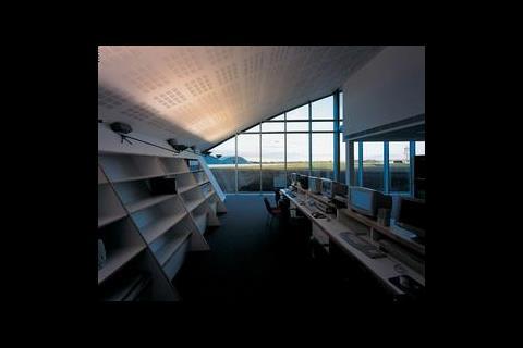
Clerestory glazing provides a limited daylight to the acr with fluorescent uplighters providing additional background lighting. Lighting above each of the control desks comprises of two specialist metal halide fittings mounted on individual lighting tracks, each separately fed from the ups systems. The dimmable fittings employ barn door attachments to focus the light onto a small area for the operator and limit spread to adjacent workstations.
Visual control
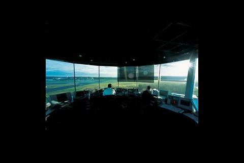
The specialist vcr was prefabricated off-site by Guildford based Alifab – effectively a design and build package which hooked-up to the services provided. The cab includes everything from the support steelwork, glazing and cladding down to the lighting and air traffic control consoles. A maximum of five controllers can be seated in a circular arrangement on the dais at the centre of the room, although there are generally only two during normal operation. Angled frameless glazing, incorporating a fine heating element to prevent condensation, wraps around the circumference of the cab, with the support steels arranged to give an unobstructed view of the main runway. To prevent solar glare a series of electronically controlled blinds hang from the ceiling, which are operated by the controllers from their desks. Lighting is again fed from two circuits, with a series of compact fluorescents arranged around the perimeter and low voltage downlighters positioned over specific desk points.
The dais acts as a service void for the cabling and supply air ductwork, which feeds a series of floor diffusers. Again the back of the control desks can be accessed from the walk way around the perimeter of the dais with minimum disturbance to the controllers.
The fire alarm system for the building operates on a double-knock basis for automatic detection, allowing controllers in the acr or vcr to check if there is a system fault or a real emergency. In order to carry out handover exercises the control manager can mute the audible alarm, giving a transition period in which any aircraft on their final approach can land before diverting inbound traffic to other airports. A visual warning continues throughout this period along with audible reminders every five minutes.
The lift is the primary transport route from the bottom to the top of the tower and is supported by the generator backed supply. Although it isn't designed to operate as a firefighting lift, in the event that the fire detection system is activated staff in the vcr can still use the lift rather than travelling the 10 floors by foot. In addition to this the lift is fitted with an integral battery back-up to allow it to do one trip in the event of all the supplies being lost.
Further development
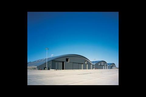
Across the airfield from the air traffic control tower, 12 000 m2 of dedicated aircraft hangarage is nearing completion. The sweeping curve of the hangar roof creates three large bays each capable of housing two Boeing business jets or a number of smaller aircraft. The 290 m long by 45 m deep building uses arches as the main structure with office space located in the zones between each of the bays. A further complex of higher spec offices are located at the eastern end of the hangar, which incorporates a fully glazed end wall and a large mezzanine level.
In contrast to the air traffic control tower, servicing for the hangar complex is straightforward. The buildings are served by electrical feeds from either end, one supplying the bays, which are set up on an individual basis, and the other the primary office space. Busbar distribution and cable trays run along the rear wall providing three-phase power, lighting, security and fire alarm systems, as well as a compressed air installation for operating tools.
High-level gas radiant heaters are mounted along the back of the space to provide a small level of heating to the bays. "These are designed to provide just enough heat to take the chill out of the air and bring it up by 2-3°C," says Johnson. Fire protection is via a flame detection system. Each bay is divided into six zones, with sensors mounted at a height of around 3 m, roughly the wing height for aircraft to coincide with the level of the fuel tanks – a worst case scenario.
Site clearance for a 4000 m2 terminal building is also getting underway, following a design which compliments both the control tower and hangar complex.
At Farnborough the designers faced an unusual situation. "Although the design of the air traffic control tower utilises standard systems, the operational characteristics coupled with the remoteness of the vcr meant the design automatically became a challenge to route all the specialist systems to their destination," says Johnson. With this taken care of Farnborough is now ready to take off.
Source
Building Sustainable Design
Credits
Client TAG Aviation – Farnborough Airport Management Contractor Bovis Lend Lease Architect Reid Architecture M&E consulting engineer Buro Happold Structural engineer Buro Happold Civil engineer Buro Happold (Buildings only) M&E contractor Goodmarriott & Hursthouse AHUs Dalair Boilers Broag Ceiling diffusers Barcol – Air UK Control valves TAC Dampers Action Air Above ground drainage Terrian DX systems (vrv) Mitsubishi – City Multi R2 Series Extract fans Nuaire Fan coil units Mitsubishi – ducted indoor units Humidifiers J S Humidifiers Pumps Wilo Radiators Hudevad Sound attenuation ATT Valves Hattersley Water heaters Heatrae Sadia Controls TAC Fire alarm/detection Techserve Lifts Otis Luminaires Zumtobel, Iguzzini, Louis Poulsen Motor control centres Farwell Engineering UPS Invensys








No comments yet