


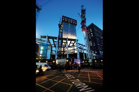
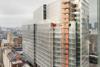
The Shard had already climbed to 21 storeys by the time 700 truckloads of concrete were poured to create its foundation. So what was stopping it from falling down?
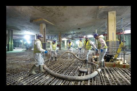
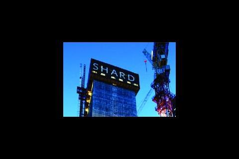
Two weeks ago, over a gruelling 36-hour operation, 700 truckloads of concrete were deposited at the London Bridge site of the Renzo Piano-designed Shard tower. The 5,500m3 single concrete pour ranks among the largest ever undertaken on a building in the capital and marks the first major milestone in the construction of what will become Europe’s tallest building. This culmination of the building’s groundworks package has created the huge raft foundation that will support the tower (see graphic below story). However, for regular commuters and passers-by it begs a question: what has been holding up the 21-storey core which over the last few months has been pushing its way into the skyline? The answer lies in the novel approach that has been used to get this building up as fast as possible.
So why the hurry? Well, a switch from construction management to a fixed-price contract had delayed the start of the Shard on site. Some way was needed of getting the programme back on track. But constructing the building in the first place was always going to be tricky. Not only does the site have to operate among the thousands of commuters that come into London Bridge station every day, but it also has to have minimal impact on its surroundings (see box, left). The site sits right up against the corner of the station which is supported on old brick railway arches, the tunnels of the Jubilee Line run underground close by and Guy’s hospital is next door. Plus, a large Victorian water mains runs below the road next to the site. It was calculated that any structure within 100m of the site’s perimeter could be at risk from any movement caused by excavating the ground and building the 306m tower.

Top-down construction involves casting the ground floor slab and excavating the ground below while work on the superstructure above can continue
“You have a very constrained site,” says an understated Kamran Moazami, director of WSP Cantor Seinuk, the structural engineer on the project. “We had to be quite careful about how to demolish the existing building, excavate down and control any movement. At the same time, whatever we did had to be the fastest way of constructing the building.”
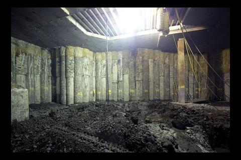
Top-down construction had been planned from the start. This enables the building’s substructure and superstructure to get under way simultaneously, thereby saving time. As soon as the seventies office block Southwark Towers – former home of Pricewaterhouse Coopers – was demolished, work began to install a secant pile wall around the site. This barrier prevents water ingress and enables construction of the basement. Ultimately it will provide crucial support at the building’s edges.
At the same time, work began on installing the support piles from ground level. This was a complicated process as Southwark Towers didn’t have a basement. Instead, relatively shallow under-reamed piles – a pile with a base that splays out – had been used to support it. In places they are so close that the bases almost touch. The difficulty was how to thread the 100-plus new piles past these.
Moazami’s team tracked down a plan of the original Southwark Towers. This was, in fact, a scan of a photocopy of a microfiche record of a hand-drawn original, which had to be stretched, scaled and rotated to correct distortions that had occurred over the years. Overlaying this onto the design for the Shard enabled the team to work out the position of the new piles. The problem was that there was no guarantee of the accuracy of the microfiche record and the 1,800mm diameter piles had to be accurately placed; hitting an existing one while installing the new piles could skew it off course, and boring through them would be time-consuming and difficult. As a contingency, says Moazami, provisions were made that once piling contractor Stent started the boring, his team was ready to redesign the foundation for any changes in position that might be needed. “Believe it or not, the positions were all spot on,” he says.

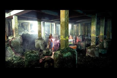
5,500m3 of concrete were poured over a 36-hour period to create the base on which the tower will sit
But the schedule still needed to be shaved down. Main contractor Mace together with concrete subcontractor Byrne Bros and specialist engineering designer Robert Bird Group began exploring the idea of “jump starting” the core. This had the potential to shave three months off the construction time, but the technique had not been used before on a building of this scale.
The initial plan had been to construct a cofferdam from sheet metal piles at the centre of the site and excavate this conventionally so work could start on the core from the base up. Meanwhile, top-down construction would be used for the area between the cofferdam and the secant piled wall.
However, jump starting meant that work on the core and steelwork above ground could go ahead while the core continued to be built downwards into the basement. It would also do away with the time-consuming exercise of installing the cofferdam.
Tim Goldby, director of main contractor Mace, likens it to building on a table top. The technique involves sinking large steel box columns into support piles directly beneath the core, which take the load as it is constructed skywards. Once the basement below is scooped out and the large raft foundation poured, reinforced concrete walls are constructed beneath the core that will then transfer the load into the raft and piles.
It might sound straightforward but it’s expensive – it requires an additional 550 tonnes of steel – and is not without risk.

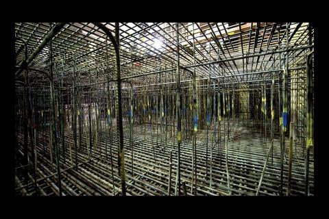
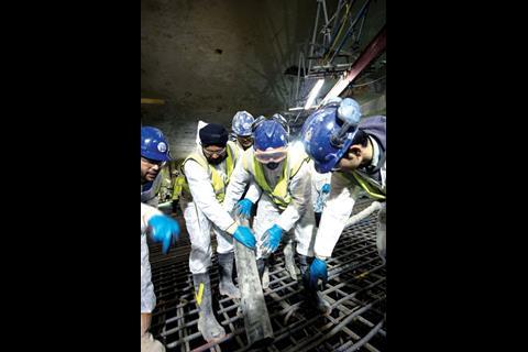
1,000 tonnes of reinforcement steel have been used in the raft foundation
“We had an open mind to it but we knew it would be difficult,” says Moazami. “One of the things we needed was to make sure there wouldn’t be any movement, which isn’t easy given you’ve got this humungous lump of concrete sitting on relatively tiny legs.”
The construction team had to ensure that the weight of the core would not cause any of the steel plunge columns to buckle before the concrete walls were put in place. There was a further complication, however, in that the underlying piles from the old Southwark Towers meant it would not be possible to arrange the columns uniformly.
The solution has been to use a total of 23 columns and set a limit on the height the core could be built before the walls were constructed. According to Rodolfo Giannini, associate director with WSP Cantor Seinuk, several design iterations were needed to get a column layout that would avoid any clash between the core’s centre of gravity and that of the pile group, which might cause differential settlement of the core.
Installing the plunge columns called for pinpoint accuracy, as they had to sit precisely within the 800mm core walls at basement level. Stent used a hydraulic frame which sits on the top of the pile casing and uses four hydraulic arms to position the 23m-long steel columns. Two gimbal mechanisms that work like a ship’s compass make sure the frame sits in the correct position before the plunge column is lifted and lowered into it. It then plunges into the concrete pile under its own weight before any final adjustments are made; it grips the column in position until the concrete sets.
Once the plunge columns were in place, work could begin constructing the core. The ground was excavated down to level two of the three-storey basement to enable the slip form to be positioned and then construction upwards got under way. As the core climbed higher, work on the steel frame and floors could also get under way.
At the same time, work excavating the more than 65,000m3 of spoil to create the basement began. This was first taken down to level two where the floor slab was cast and then down to level three where the huge raft foundation that will transfer the building’s weight into the piles is positioned.

Once the raft foundation is in place and levelled, work can begin on the support walls between the slab and the underside of the core
According to Don Houston, senior project manager with concrete contractor Byrne Bros, the initial plan was to cast the foundation in a number of sections. “We had the idea of doing it in one go as an aspiration but when we started looking at it in more detail it became apparent that there were significant practical difficulties in splitting this pour up because of the amount of reinforcing steel in the raft.” In places, there are up to seven layers of densely packed, 40mm-diameter rebar which made it very difficult to get a stop in to split up the pour. “That aspiration moved to the top of the list and eventually became a must, but pouring it as one big lump also meant we could control the shrinkage” (see below).
As well as shaving time off the programme, the top-down construction has had a health and safety advantage. “We have managed to de-risk this part of the project considerably by segregating the excavation and the concreting, which traditionally would overlap,” says Goldby. The upshot is more than 250,000 man hours with no accidents.
Throughout the construction, the team has monitored the facades of all the buildings along St Thomas Street next to the site as well as the tunnels to the Jubilee line and the brick arches supporting the station concourse. So far, the nearest Jubilee line tunnel has moved closer to the site. “This agrees with our predictions,” says Giannini, who says it was calculated to move a total of 15mm in that director during excavation and that it will move back by 4mm with construction of the tower.
With the huge concrete pour now having taken place, the next stage is to construct the walls from the slab raft up to the base of the core. This needs to be flawless, as any gaps between these walls and the bottom of the core will cause it to settle as more weight is added. For this, the team has a solution: to pump self-compacting concrete from the base of the wall shuttering upwards to ensure a snug fit. Only then can the core continue its inexorable climb upwards.
A tight site
If the technical challenges of constructing Europe’s tallest building were not enough, the Shard’s construction team also has to grapple with the logistical nightmare presented by a constrained site in a bustling part of London. As well as the thousands of commuters coming into London Bridge station every day, there is also a bus station on the doorstep which has to remain running. On top of this, Guy’s hospital is across the road from the site’s main access gate. Together with pedestrians constantly swarming the area and narrow access roads, moving materials to and from the site is a major challenge.
At the peak of the recent concrete pour, trucks were arriving on site at two-minute intervals. Three concrete pumps were installed that were capable of pumping up to 150m3 an hour to enable the turnaround time needed to keep the trucks running. These were coming from four batching plants from as far as Greenwich in the east and Battersea in the south. According to Don Houston, senior project manager with concrete contractor Byrne Bros, this was to spread the risk. “We could probably have got away with using two plants, but if one goes down you lose 50% of the capacity. This way there is less risk.”
The whole operation was scheduled for a weekend when the traffic was quieter and there was less demand from other sites in the capital.
Tim Goldby, director of main contractor Mace, says a lot of experience on lorry movements was gained when they were carrying out the bulk excavation, when trucks were leaving the site every three minutes. “We worked out primary and secondary routes for the trucks and planned it all in consultation with Southwark council and all the major stakeholders.”
Lorry deliveries to the site are strictly controlled with a buffer zone a few miles away where vehicles are held and dispatched to site at regular intervals.
Getting to the starting line
Before the demolition could get under way on the existing Southwark Towers and construction of the Shard could begin, there was the small issue of the enabling works.
These were extensive. Demolishing Southwark Towers wasn’t straightforward. The structure helped laterally restrain a number of the old brick arches on which London Bridge station is constructed and these first had to be tied back to prevent them moving.
On top of this, part of the supporting structure for the bus station concourse protruded into the basement of the existing building and had to be demolished to make way for the second floor level of the new building. To allow the bus station to remain operational, mini piles were installed in a confined area with concrete foundations and steel columns used to prop up the concourse.
A corner column of the train shed roof at London Bridge station also lies within the site and the slab around this column had to be broken out to make way for the setting out of the building. This column is listed and steel supports have been positioned beneath it to allow the slab to be demolished around it.
With both of these new supports, hydraulic jacks have been incorporated into the bases. “We are constantly monitoring the position of these structures and if there is any movement, we get an alert and we can compensate for it by jacking up the support,” says Roma Agrawal, structural engineer with WSP Cantor Seinuk. So far this has only been needed once.
Along the line of the western secant pile wall were two disused vertical shafts. One, a stair shaft, had been backfilled in the fifties. But before work on the secant wall could begin, the entire shaft was removed from within a temporary works cofferdam. The other, a lift shaft, was filled with foam concrete before piling could begin. The shafts couldn’t have been in a worse place, but the work was needed to stabilise them and prevent water ingress once the secant wall was installed.
Into the mix the concrete pour
At around 5,500m3, the concrete pour to create the raft foundation to support the Shard was among the largest undertaken on a UK building, if not Europe. As such, a conventional concrete mix would not do. When concrete cures it generates heat and the sheer volume of the pour, which measures about 50m by 60m and is up to 3m deep in places, means that the high levels of heat produced could result in shrinkage and cracking.
According to Don Houston, senior project manager with concrete contractor Byrne Bros, the overriding specification from WSP was to limit cracking. “What we needed to avoid was a large temperature differential between the centre and the top surface of the raft, so we had to look very carefully at the mix design.”
Houston is coy about the exact formulae because of the time and cost it has taken coming up with it. However, he will reveal that it uses ground granulated blast furnace slag to replace 75% of the cement, which helps limit the amount of heat generated.
The downside of using a cement replacement is low early strength gain – 56 days compared with 14 for a mix using Ordinary Portland cement – so the mix was developed to make sure it would achieve sufficient strength gain over the first 14 days to meet the structural requirements, with the full strength coming later.
The concrete also needed to flow easily around the densely packed reinforcement bars at the base of the slab. Additives – plasticisers, retarders and others – were included to give good flow characteristics, delay setting times and prevent “bleed”, which is a common result of using high levels of cement replacement.
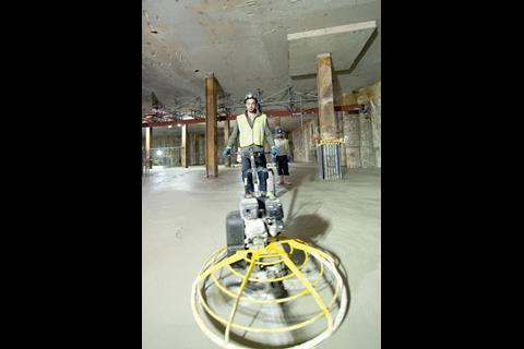
The concrete was poured in layers 750mm deep. This helped limit heat build-up and also regulated the placement so that succeeding layers could be poured before early layers had set.
A computer programme was created to predict the temperature of the core, and thermocouples were fixed to the reinforcement cage in the raft to enable the temperature to be monitored. The mix recipe could then be altered at the batching plant if needed.
To limit heat build-up in the confined space while the pour was under way, fans were used to draw air through the basement and ventilate it out through the mole hole where the excavation occurred.
Original print headline - Foot of the mount in
Project team
client Sellar Properties
concept architect Renzo Piano Building Workshop
detail architect Adamson Associates
structural, geotechnical and acoustic engineer WSP Cantor Seinuk
M&E engineer Arup
main contractor Mace
cost consultant Davis Langdon
piling subcontractor Stent Foundations
concrete subcontractor Byrne Bros
construction engineer Robert Bird Group
steel frame contractor Severfield-Reeve Structures
Downloads
The lowdown on top-down
Image, Size 0 kb


3 Readers' comments