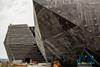
Kengo Kuma’s extraordinarily complex design for the V&A’s outpost in Dundee would not have been possible without 3D modelling and analysis tools, not to mention complex construction techniques, that have left the city with a building of true grit

Construction

Given the recent frenzy of construction activity emanating from some of our major cultural institutions, it’s hard to believe public funding for the arts is under any pressure. At £260m, Tate Modern’s new Switch House was one of the more extravagant and high-profile buildings to be built after the 2007 financial crash. Never one to be outdone, Tate St Ives now has a construction team busily burrowing deep into a granite hillside to create a new extension. And now the mighty V&A has jumped onto the same totemic bandwagon as Tate and engaged the Japanese architect Kengo Kuma to design his first major building in the UK – a distinctive new gallery for the citizens of Dundee.

In a classic case of arts-led regeneration, the V&A Dundee sits on the banks of the River Tay, the city’s former industrial zone. The building has a solid, somewhat austere, gritty appearance, with the structure formed from black concrete walls cantilevering out from the base like the hull of a ship. Part of the building juts into the river Tay, emphasising the building’s maritime connection. Some areas of wall are clad in stone planks, giving the building a striated appearance similar to exposed layers of sedimentary rock in a cliff face.

Concrete walls

The concrete walls curve in plan and twist in section making construction a challenge

This structure is extraordinarily complex and is best appreciated close up. The footprint of the upper, second-floor galleries is much larger than the base, and the floor is supported by structural concrete walls that cantilever outwards from the base of the building. The structural piece de resistance is that these cantilevered walls also curve in plan and twist in section. “The wall looks like a wave, the sort of thing you see surfers riding on in Hawaii,” says Malcolm Boyd, the construction manager for contractor Bam. “The angle of the walls range from 23 to 87 degrees and they curve at the same time.” He says the geometry can be likened to a deck of cards which are twisted 90 degrees from the bottom card to the one at the top. Each card has a straight edge although the whole pack describes a curve. The geometry is so convoluted that in places the walls are like two packs of cards twisting in opposite directions – an area of wall curves in section in one direction and switches to the opposite direction in the space of a few metres. And the enormous second floor of galleries has just two columns to help support the roof.

Boyd is the man responsible for delivering this unusual project on time and budget.

A veteran of concrete, he says he has only delivered three steel buildings in his 25-year career. Bam had to be absolutely confident of getting this complex job right as it has taken the job on a single stage traditional contract for £70m. Boyd says the secret of success is lots of careful planning and co-ordination months in advance of the work taking place. “We do a lot of risk management and try and manage the process upfront,” he says. There is also a strict regime of constant checking and double-checking complex parts of the job to make sure nothing falls out of line.

The wall looks like a wave, the sort of thing you see surfers riding on in Hawaii

Malcolm Boyd, BAM

The part of the building jutting into the river was one of the early challenges on this job.

A cofferdam had to be constructed to keep the river at bay while this part of the building was realised. This meant working around the maritime life in this part of the river, namely seals giving birth. “This was a critical part of the project; if we had moved into the seal pup season that would have delayed the job by up to 12 weeks,” says Boyd. Work started in March 2015 and had to be complete by the end of May.

The cofferdam is formed from 15 sheet pile lined cells filled with rock first built out from the river bank then parallel with the river bank to create a dry zone area within the riverbed. This was done by two teams, with one building out from the east side and the other from the west until they met in the middle.

Entrance

The forces generated by the outward leaning walls are tied back to the core using huge trusses at roof level. This enabled the creation of a largely column-free, second-floor gallery

River sediment was scooped out from the area enclosed by the cofferdam then filled in with compacted aggregate.

A contiguous piled wall was driven into the aggregate to support the front of the building in the riverbed. The aggregate in the gap between the contiguous piles and cofferdam was scooped out and a reinforced concrete wall built in front of the piles. This wall is architecturally important as it is visible at low tide and was dyed black; the same colour has been used for the rest of the external structure. The wall also features a wave break at the top to minimise the amount of water splashing over the building. Meanwhile, piling for the rest of the structure was taking place on dry land.

Structure

To understand how the walls were built it helps to appreciate the overall structural solution. The building consists of two connected volumes. Part of building A extends into the river while B sits entirely on dry land. The two volumes are separated by a triangular arch at ground and first-floor level. Building A includes a large entrance space with walls that will be lined with oak planks to echo the exterior. It will also include restaurants and toilets. Building B houses the back-of-house areas including offices and loading bays. The two volumes are joined at second-floor level to create a large, uninterrupted gallery space for exhibitions.

The building features two cores – one for A and one for B. Spine walls radiate from the cores to pick up the tension loads imposed by the lower part of the external walls leaning outwards. The external walls are also restrained by steel beams connected back to the core at first-floor level. Huge, 2m deep steel trusses up to 28m long are employed at roof level as these have to restrain the walls without intermediate columns. “The central core could be you with your arms stretched out holding your shopping bags,” explains Graeme Moncur, the associate at Arup who is responsible for the structural engineering. “The beams are like your arms – these stop the walls from falling out.” He adds the

In practice this meant the walls wouldn’t stand up unsupported until the

Early aerial view of shuttering

The walls were constructed using bespoke shuttering, which was supported by Peri’s standard falsework system

intermediate floors and roof were on. This meant extensive propping and substantial foundations to support the weight of the walls and temporary works. Steel driven piles were installed on a 3m x 3m grid around the building perimeter and topped with a heavily reinforced slab. “That allowed the temporary works to take the full load of the building,” explains Boyd.

A large perimeter ground beam was constructed over the piles ready for work to start on the walls. Creating the bespoke formwork needed for the walls was a big, complex job undertaken by specialist Peri. “Every single shutter was bespoke and single use only,” says Boyd. There were 20 designers and a team of 50 joiners working on the shutters in five different offsite locations and 30 joiners working onsite.

The beams are like your arms – these stop the walls from falling out

Graeme Moncur, Arup

The bespoke shutters were supported by Peri’s standard falsework system. This combination continued to support the building after the concrete had been cast. Each shutter consists of a flat sheet of plywood sitting against the falsework. A lattice work of plywood similar to that in a wine box was used to create the complex curvature of the wall – the ends of this latticework was cut to shape using CNC cutters. Thin sheets of ply were folded over this latticework to form the surface of the shutter ready for the concrete. As the shuttering had to transfer the loads from the walls back to the falsework, the latticework of ply had to be strategically strengthened in places with timber sections to take the loads.

Boyd explains laying the rebar was a tricky job. The bars are curved – the diameter of some of these were too thick to be bent on site and were supplied pre-curved from detailed supplied by Arup. Setting out the rebar was challenging on walls with complex geometry and was done by engineers on site.

Construction

The concrete planks weigh up to 2.5 tonnes each. The planks feature cast in hooks enabling these to be quickly hooked onto fixings attached to the concrete walls

The complex geometry meant concrete couldn’t be poured into the shuttering a floor at time because of the risks of voids in the concrete. Instead each floor was cast in three lifts with the pouring sequence determined by the specific geometry of each section. “We spent a lot of time reviewing the design before pouring,” explains Boyd. He adds it was hard to predict the loading on the falsework so each pour had be analysed and extra propping brought in to deal with load hotspots.

By June 2016, the walls were up to first-floor level. Heavy metal plates were used to connect the walls to the steel beams transferring the tension loads back to the core. The largest plate measured 1.38m long by 1m high and 58mm thick. Steel fin plates were welded to the metal plates ready for connection to the beams. These had to be accurate to within 3mm so the bolt holes in the beams would line up with those in the fin plates when the beams were positioned.

Entrance

The concrete walls, floors and roof structure needed to be finished before the temporary works supporting the building could be removed

The second floor walls are relatively vertical compared with the contorted lower part of the structure. But these still twist and curve up to roof level. Once the huge, 2m deep roof level trusses were in place secondary beams were installed over the trusses then the roof covering could go on. Only then could the forest of temporary works surrounding the building be taken down. “As soon as we got the roof lining in place we could start stripping the shutters,” says Boyd. This started in January this year and took nearly two months. As the large, dark sculptural hulk of the building was unwrapped, the citizens of Dundee got their first sense of what this unusual building would look like.

With the walls completed, work could start on fixing the stone plank cladding. This is actually made of precast concrete planks with a rough, exposed aggregate to give the appearance of stone. Halfen fixings are carefully set out and attached to cast in slots in the walls. The planks weigh up to 2.5 tonnes each so a robust fixing system was needed. A neat solution has been devised – each plank includes two cast in metal hooks. The planks are lifted into position using a mobile crane and simply hooked over the wall fixings. A locking bolt prevents the planks from unhooking. The planks are all set at the same angle regardless of the wall below. An adjustable, threaded metal rod cast into the walls is used to get the angle of the planks right.

Aerial view

Aerial view of building showing the two volumes making up the building. The roof structure is being assembled after completion of the concrete walls

The precast plank installation on the river side of the building is almost complete. The team will switch to the city side of the job so work can start on the landscaping next to the river. The landscaping includes ponds to give the impression that the building is emerging from the river. Visitors will approach the building along the new marine wall with the river on one side and the ponds on the other to give the impression they are crossing water over a bridge.

Cofferdam removal work will start in July. Internal fit-out began during the first part of 2017 and is scheduled to complete by January 2018, ready for building handover to the V&A. The V&A will bring in its furniture and equipment ready for a late summer opening. Given the powerful architectural qualities of this building and the technical challenges involved in delivering it, the V&A could be said to have got itself a reasonable deal.

Cross section through building A and B diagram

3D model of structure. The outward leaning walls (pink) are tied back to the core (green) with steel beams (blue) at intermediate and roof level

3D modelling the V&A

The V&A Dundee would have been almost impossible to realise without 3D computer modelling and analysis tools. Kengo Kuma designed the complex external walls and precast concrete cladding planks using the 3D modelling tool Rhino. Arup’s Graeme Moncur says the firm had to take this complex geometrical shape and find a way of making it stand up. The first challenge was to transfer the architectural geometry into Arup’s inhouse finite element analysis tool GSA. The Rhino model was broken into layers to separate out different parts of the structure. Parametric modelling package Grasshopper was used to generate an analysis mesh for the external walls, which was imported into GSA where the structure could be fully analysed. Arup worked with Kengo Kuma to tweak the design to reduce areas of high stress. This involved reducing the angles of some of the exterior walls. The model was also used to create a 3D immersive VR environment to help designers and clients understand the complex design.

Project team

Client Dundee council
Concept/Lead architect Kengo Kuma & Associates
Executive architect James F Stephens
Structural and MEP engineer Arup
Project manager Turner & Townsend
QS CBA
Contractor Bam
Concrete specialist Careys
Engineer to Careys Alan White Design
Bespoke formwork Peri

Visualisation

Visualisation showing building from the River Tay

A troubled start

The idea of a V&A in Dundee came from initial discussions between the University of Dundee and the V&A as far back as 2007. Other organisations including Dundee council, Scottish Enterprise and Abertay University became interested and formed the Design Dundee Company to realise the project. A benchmarking exercise established a budget of £27m based on the per square metre cost of £4,500/m2 for a 6,000m2 building. Benchmarked buildings included the Zaha Hadid-designed Glasgow Transport Museum, which was completed in 2011 at a cost of £6,700 per m2 and the Museum of Scotland, which was completed in 1998 at a cost of £6,200 per m2.

A competition was launched in 2010 with a budget of £27m and was won by Japanese architect Kengo Kuma. Kuma was appointed in 2011 and worked up the design for a building wholly constructed in the River Tay.

In 2011, Dundee council agreed a budget of £45m for the project. Costs continued to escalate and in 2012 the idea of constructing the entire building in the river was dropped to save money. The building was redesigned to sit on the riverbank.

The project was tendered in 2013 and in 2014 only two tenders were submitted – by Sir Robert McAlpine and Bam. Both tenders exceeded the budget and were close to each other. In 2015, a new budget of £80.1m was approved by the council.

An independent report by businessman John McClelland into the cost increases concluded there was a mismatch between the aspirations for the project and what was affordable, saying there was little prospect the building could ever be realised for the original budget. The original cost benchmark was for a standard building but the selected design was for an “elite” building constructed over water.

It also found there was insufficient external professional support for the project, especially during the early stages, and it was “unlikely” construction inflation had been fully factored into the budget.