


Sponsored by SOPREMA, this module examines the common gap between as-designed and as-built thermal efficiency, asking how insulation can be key to bridging this gap and looking more broadly at the move from a culture of tick-box compliance to evidence-based building performance

The performance gap is a critical challenge for the construction industry. Tighter Building Regulations and net zero targets now require building envelopes to evidence a high standard of thermal performance so as to reduce operational energy use. However, gaps between as-designed and as-built performance mean built structures often struggle to achieve compliance – which can lead to costly remedial works and delays. But careful specification and installation of the right insulation can play an important part in preventing problems.
Learning objectives
- Know the energy performance requirements in Approved Document L of the Building Regulations.
- Understand what is meant by the performance gap in energy efficiency and what causes it.
- Recognise the best ways to prevent this performance gap.
Thermal efficiency standards
The drive to improve the thermal efficiency of building fabric began in the 1970s after the oil crises. The first limits were introduced into the Building Regulations in 1976. Since then, targets have become increasingly demanding, as we respond to the climate crisis.
Today’s performance standards for conservation of fuel and power – energy performance – are set out in the Building Regulations Part L, also known as Approved Document L (ADL). This gives detailed requirements for new-build and refurbishment projects in England. Similar regulations exist in Wales, Scotland and Northern Ireland. ADL is divided into two volumes: volume 1 applies to dwellings, while volume 2 to other buildings. For mixed-use developments and multi-occupancy buildings, both may need referencing. Minimum thermal efficiency standards are given for building elements – walls, roofs and floors – rather than for individual materials. These are given as U-values.
The U-value is a measure of thermal efficiency. It describes how quickly heat passes through a building element – such as a wall, floor or roof – from inside to outside and is expressed in W/(m²K) (watts per metre squared kelvin). The lower the U-value, the slower the heat loss, and the more energy efficient the element. So, for example, if a window has a U-value of 2W/(m²K), then for every degree difference in temperature between inside and outside, 2W of heat is lost through every square metre of window.
The 2021 update to ADL introduced stricter limiting U-values than previously. For example, the requirements for new-build dwellings are:
- External walls 0.26W/(m²K)
- Roofs 0.16W/(m²K)
- Floors 0.18W/(m²K).
Requirements for buildings other than dwellings and for refurbishment projects are set out separately, as are those for new-builds and extensions to existing buildings. Because the values vary depending on building type and building element, you should always consult the relevant volume to confirm the correct value.
It is important to note these are limiting values – minimum requirements. ADL makes clear that, in practice, lower U-values will often be necessary to meet overall fabric energy-efficiency targets. So designers often work to a notional or target value that is lower that the legal limiting value. For example, while the limiting value for walls is 0.26W/(m²K), the notional/target value for walls that designers usually work to is 0.18 W/(m²K).
Designed performance versus actual
However, producing energy-efficient buildings is not a simple matter of designing to the target U-values – equal attention must be paid to how they are built, because designed performance is no guarantee of actual performance.
Research from a whole range of sources, such as Innovate UK’s Building Performance Evaluation programme, the Zero Carbon Hub, the UK Green Building Council and various academics, has shown a gap between design intent and real-world performance. Many buildings with A-rated EPCs turned out to be delivering operational performance more like that of C-rated buildings. In fact, many new buildings have been found to use two to three times as much energy as predicted.
This difference between a building’s predicted performance as it was designed and its actual performance once built is known as the performance gap. Performance gaps have been found in various aspects of construction – including operational costs, airtightness, occupant comfort, indoor air quality, and the long-term integrity of structure and fabric – as well as thermal efficiency.
This particular performance gap can have severe implications for a building’s compliance with building regulations and sustainability targets.
ADL and other national legislation, along with local authority planning requirements, all increasingly demand evidence of as-built performance. If those performance requirements are not met, additional work will be required before building sign-off is granted – which can mean delays and added expense. Closing the performance gap requires accurate product specification, careful detailing and on-site practices that help ensure the designed performance is delivered.
What causes the gap? Issues with commissioning and procurement can compromise performance, but three main factors are critical: over-optimistic assumptions at design stage; changes during construction – swapping insulation type or thickness without recalculating U-values; and poor workmanship during installation – for example, misaligned insulation boards could change the whole-building performance.
Design-stage calculations often assume ideal conditions, such as continuity of insulation, airtightness and consistent workmanship, and these assumptions are not always achieved on site. Even small deviations in workmanship, product selection or detailing can add up to a significant shortfall in thermal performance.
Closing the performance gap
Closing the performance gap requires accurate product specification, careful detailing, and on-site work practices to ensure the designed performance is delivered. Strategies that can help include:
- Providing clear, detailed specification guidance
- Using the specified insulation
- Following manufacturers’ installation guidance
- Ensuring a continuous insulation layer to reduce thermal bridging and gaps
- Improved on-site training and oversight – for instance, training installers to maintain insulation continuity and seal penetrations properly
- Focusing on junction detailing to stop heat loss
- Improved on-site collaboration between designers, specifiers and installers
- Performance validation – thermal imaging and airtightness testing during construction can spot problems early.
Insulation is key to achieving the thermal performance requirements set out in ADL, but not all insulation products are the same. Variations in thermal conductivity and thickness can influence thermal performance.
Specifiers will be looking for insulation with a low λ-value (lambda value), which means low thermal conductivity. The λ-value is a measure of how well a material conducts heat – how easily heat flows through it. Denoted in W/m·k (watts per metre per kelvin), it measures how many watts of heat flow through one metre thickness of the material for each degree of temperature difference between its two sides. The lower the λ-value, the more effectively the material resists heat flow.
Of course, other considerations, such as moisture resistance, acoustic performance and compressive strength, also need to be taken into account, and will all contribute to insulation’s suitability and long-term performance.

Thermal bridges
As noted already, specifying low λ-value insulation does not guarantee that a building will be thermally efficient. When theoretical values are not delivered in practice, this is often related to installation – typically thermal bridging and poor detailing at junctions and building penetrations.
A thermal bridge, also known as a cold bridge, is any part of a building envelope where heat flows out more easily because insulation is missing, thinner, or bypassed by a more conductive material. Sites vulnerable to thermal bridging include:
- Junctions between different parts of a building – roof–to-wall, wall–to-floor and so on
- Around windows and doors
- Balcony connections
- Steel beams or concrete elements – which are more conductive – that penetrate insulation
- Poorly insulated cavity closers and sills.
Thermal bridges can account for as much as 20%-30% of the heat loss in a typical new-build home, and, as homes become better insulated, thermal bridges are becoming even more of an issue. The cold spots they create can also lead to a risk of condensation and mould, reduced internal surface temperature (comfort issue) and poorer Standard Assessment Procedure (SAP) and Simplified Building Energy Model (SBEM) results.
Steps you can take to avoid thermal bridging include:
- Use thermal-bridge analysis software, such as THERM or Psi-Therm, to identify weak spots, model and check junctions to calculate ψ-values (psi-values – see below) and verify design performance. The ψ-values must be modelled in accordance with BS EN ISO 10211 Thermal bridges in building construction – Heat flows and surface temperatures – Detailed calculations, and the modeller should follow BR 497 (2016) Conventions for Calculating Linear Thermal Transmittance and Temperature Factors the UK guidance on thermal bridge modelling.
- Use recommended junction details – adopt pre-tested, accredited detailing with known ψ-values.
- Keep insulation continuous – design insulation layers to form an unbroken thermal envelope
- Align wall, floor and roof insulation layers without gaps or misalignments
- Wrap insulation around corners, window reveals and upstands – paying attention to sill and threshold junctions
- Use thermally broken or insulated components – such as thermally broken lintels, cavity trays, wall ties and brackets – and thermal-break connectors for balconies or canopy beams
- Minimise conductive materials in the structure and avoid running steel or concrete directly through insulation layers
- Ensure window and door frames overlap insulation where possible
- Use insulated cavity closers and continuous damp-proof courses that don’t interrupt insulation
- Use lightweight or aerated concrete blocks at junctions
- Review ψ-values and redesign high-loss areas early in design
- Enter measured ψ-values into SAP or SBEM assessments to reduce default penalties.

Junctions
Junctions are a high-risk area for thermal bridging. The rate of heat loss at a junction is measured as a ψ-value (psi-value), which is expressed in W/m·K. This represents heat loss per metre of junction length per degree of temperature difference. Lower ψ-values mean less heat loss. χ-value (chi-value) is the measure of heat loss through a single-point thermal bridge, such as a single fixing, bolt, or bracket that penetrates insulation.
The following are some suggested methods for preventing problems at junctions.
Roof-wall junctions
Insulation often becomes thinner, compressed, or stops short at the eaves of cold pitched roofs. This may be due to interruptions from structural elements or to the need for a ventilation gap.
To support thermal performance, insulation depth should be maintained to the wall line. A stub-ended truss can create the additional depth needed for full-thickness insulation. Proprietary eaves ventilation trays help maintain a clear airflow path at the eaves and can reduce wind-washing, thereby limiting the risk of thermal bypass in this area, and a continuous air and vapour control layer below the insulation helps prevent moisture from entering the roof void.
For full-fill cavity walls constructed with polyisocyanurate (PIR) thermal insulation board, correct installation at the eaves is essential for maintaining thermal continuity. This includes:
- Clearing mortar snots and debris from the cavity to allow a close fit between the insulation and the structure
- Ensuring the gap between the wall plate and the eaves ventilator is filled with flexible insulation
- Sealing the wall plate with a continuous layer of mortar
- Sealing the gap between the wall and the ceiling linings – as well as all penetrations – with a flexible sealant or plaster mortar.
Wall-floor junctions
Thermal bridging is also a common risk where external walls meet the ground floor. This applies to both slab-edge constructions (where the edge of a concrete floor slab meets the wall) and beam-and-block floors (where precast beams and infill blocks form a suspended floor).
To reduce heat loss at these junctions, continuous perimeter insulation should be installed around the slab edge. Due to the complexity of the junction and the presence of structural elements, perfect insulation continuity between the wall and floor is not possible. However, an insulating perimeter upstand, combined with a filled cavity at damp-proof course level, can help to maintain thermal performance.
For full-fill cavity walls made with PIR thermal insulation board, advanced detailing at the ground-floor junction supports both thermal and moisture performance. Key installation requirements include:
- Installing a thermal insulation board as a vertical upstand. This should be flush with the floor finish and tight against the internal masonry
- Removing mortar snots and debris to ensure a tight fit with the structure
- Ensuring correct placement of the insulation boards
- Avoiding ground contact or protecting the boards with a suitable damp-proof course where necessary
- Installing the boards in a staggered pattern to avoid continuous vertical joints between boards
- Applying flexible sealant between the wall lining and the floor linings, as well as between the skirting board and the floor screed/finish.
Windows and doors
Windows and doors are another problem area. Heat loss through windows and doors is often exacerbated through poor detailing at jambs, heads, sills and reveals. To improve thermal performance, a continuous layer of insulation should be installed around each opening, and insulated cavity closers should be used to help reduce heat loss. Windows should be recessed into the cavity rather than flush with the inner masonry leaf as this provides space for additional insulation.
Insulated plasterboard can be used at window reveals to provide both insulation and an internal lining in one product, helping to keep the build-up thickness to a minimum. Ensuring windows and doors fit squarely within the opening also prevents insulation compression, helping to preserve thermal performance and airtightness.
For full-fill masonry cavity walls made with PIR thermal insulation board, recommended detailing includes:
- Using fully insulated and continuous cavity closers, which should be installed tight to both the insulation and cavity apertures
- Removing mortar snots and debris to ensure a close fit
- Using additional wall ties near openings to meet structural requirements (but avoid penetrating the board, as this may introduce the risk of moisture ingress)
- Sealing all joints and penetrations.
Other common areas where detailing issues can lead to thermal bridging, heat loss and condensation include: lintels; party wall edges; balconies, canopies and cantilevered slabs; intermediate timber floors and joist ends into external walls; service penetrations; parapets, flat-roof upstands and dormers; and corners. In each case, similar attention to detailing using the correct insulation products will go a long way towards solving the problem.
Choosing the right products
PIR rigid insulation boards offer high thermal performance, with typical λ-values (lambda values) around 0.022W/m·k, and are dimensionally stable when installed within a protected build-up. PIR boards also provide sufficient compressive strength for most standard building applications. The right boards will support good practice on site too. Selecting boards that are easy to handle and simple to cut can support good site practice and reduce the risk of gaps, thermal bridging and air leakage that may affect as-built performance. Good workability helps ensure tight joints and continuity of insulation, contributing to more consistent thermal outcomes.
Look too for manufacturers that offer technical guidance and installer training to promote best practice on site, as this helps reduce the risk of poor workmanship and performance-reducing mistakes.
Verification and compliance processes, combined with products designed for ease of installation and reliability, can reduce the performance gap. Specification should always consider on-site installation practices as well as an insulation product’s declared thermal properties.
Performance verification
For decades, building design and compliance in the UK have been based on the predicted performance of buildings and materials. Computer models like SAP for dwellings and SBEM for non-domestic buildings used desktop calculations to demonstrate compliance with ADL and generate energy performance certificates (EPCs).
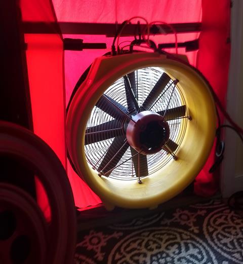
But because of performance gaps – and a collective desire to achieve real rather than notional decarbonisation – the industry is increasingly moving towards evidence-based performance verification instead. Technology and new testing techniques are supporting this. Air-pressure testing using the blower door test is standard for assessing airtightness, while heat transfer coefficient (HTC) testing evaluates the building fabric. Smart sensors can monitor ongoing energy use in existing buildings. HTC is the rate of heat loss from a building per degree of temperature difference between inside and outside. It is expressed in watts per Kelvin (W/K). A lower HTC means the building loses less heat, so it is more thermally efficient.
HTC testing is a whole-building measurement carried out on site, after construction. It often uses one of these methods:
- A co-heating test in which the building is heated with electric heaters and the inside is kept at a steady temperature above the outside. Energy input and temperature difference are monitored over several days.
- Smart or dynamic methods, such as SmartHTC, QUB or Lowe’s method, which can be done in shorter time periods and normal occupancy conditions. Sensors record internal and external temperature data.
There is a new British Standard for evaluating building performance that is aimed at helping to close the performance gap and supporting the move towards evidence-based performance.
BS 40101: 2022 Building performance evaluation of occupied and operational buildings – code of practice sets out the specification for building performance evaluation of occupied and operational buildings (using data gathered from tests, measurements, observation and user experience). It provides a framework for testing and benchmarking building performance.
The move towards evidence-based performance measurement is increasingly reflected in regulatory requirements. The 2021 update to ADL prescribed that as-built fabric and building services systems must be consistent with design-stage SAP or SBEM models – and introduced mandatory as-built verification. In a change aimed at moving the industry from tick-box compliance to evidence-based performance, photos, airtightness and commissioning test results plus updated SAP/SBEM models are now required to prove the built building performs as designed.
Similarly, the Future Homes Standard may well demand evidence of as-built performance. Other tools, documents and benchmarks that reflect this trend include: the Digital Building Regulations England Part L, the Post-Occupancy Evaluation Framework, Government Soft Landings, NABERS UK, RIBA 2030 Climate Challenge, LETI and the Building Safety Act. Meanwhile, technology – such as smart building sensors, digital twins, thermal imaging and smart meters – is facilitating the necessary monitoring.
Regulators, industry bodies and clients are moving away from “design-intent compliance” towards measurable, evidence-based verification. This is a profound shift that moves responsibility from designers alone to the entire project team.
It demands ongoing engagement during construction and after handover, and encourages learning loops across projects. The new approach aligns with net-zero commitments – where only measured performance counts.
Insulation – and its correct specification and installation – has an important role to play in delivering thermal performance that matches designed intent, and helps minimise the performance gap.
Please fill out the form below to complete the module and receive your certificate.