


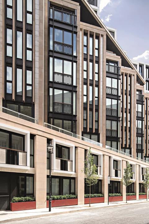
Seemingly straightforward facades like this one at Lincoln Square can develop into highly complex systems requiring extensive secondary supporting structures and bespoke fixings, explains Szerelmey
Szerelmey accounts for one of the leading design teams in our sector. Our in-house design team of ten consists of designers, engineers, design technicians and architects, and is supplemented by our satellite team of a further seven. In addition to design of stone cladding, interiors, hard landscaping, faience and restoration, the team is actively involved in the research and development of bespoke fixing systems, the use of innovative materials and solving complex design issues.
It is not uncommon for a finished facade that is apparently simple to hide a myriad of complexities behind its outer skin. Inevitably these complexities equate to cost and programme implications which may or may not have been considered at the inaugural stages of the project and can therefore cause the client QS problems. So why do seemingly straightforward facades in early design drawings develop into highly complex creatures requiring extensive secondary supporting structures and heavily designed bracketry and fixing systems?
Simply put, it boils down to design detail and joined-up thinking, both of which for different reasons do not always happen early enough in design development. This can result in gaps in the design build-up – these can be rectified at contract stage by the specialist subcontractor’s design team – but this can result in unexpected costs and delays. There is always a solution, but it can pay to engage with the subcontractor’s design team much earlier in the process so the problem is addressed, before it grows legs.
Looking at the bigger picture, the client has a vision for their building which is translated by the architect’s preliminary drawings into something real and wonderful. Engineers are engaged and they look at the drawings with the primary function of how to hold the building up, how to make it work in engineering terms. Fantastic. But the relationship between the primary structure and the ever so important cladding (that ultimately defines how a building appears) can be overlooked and this can have a significant knock-on effect. So the preliminary structural drawings done so early in the process determine where the primary structure ends, but all too often there are no details or structure where the stone or faience cladding can be fixed back to nearby. This can be solved through the use of secondary steelwork and substantial fixing systems, designed by the specialist subcontractor, that allow the load to be distributed and the material attached. However, if this situation was addressed at the start of the process, and primary structure provided in the right place to take the load of the facade, then the need for the steel would be reduced. Now, we know that sometimes primary structure is deliberately reduced because of space implications or indeed the need for more insulation to meet the equally important thermal performance of the building, but often this can be counterproductive as the large amounts of heavy steel required to ultimately support the cladding are not thermally efficient either and can actually lead to large heat losses and condensation risks locally. Another situation that quite often manifests is when the layout of fenestrations is altered after the structural drawings have been completed. Again, this can and often does have major implications in the fixing back of surrounding stonework, where structure is missing.
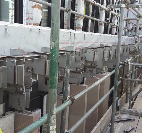
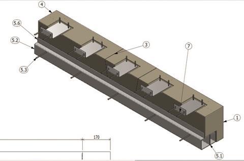
Lincoln Square is a project with a seemingly straightforward facade with 400 rhythmic piers and columns, but behind the facade sits complicated secondary steelwork. The piers were prefabricated and post-tensioned with stainless steel threaded bars to unitise elements of the facade for quicker installation/programme saving. The image above depicts the forest of secondary steelwork required to not only restrain the top of the piers but also to support the stone parapet and accommodate live loads generated later by abseilers cleaning and maintaining the facade.
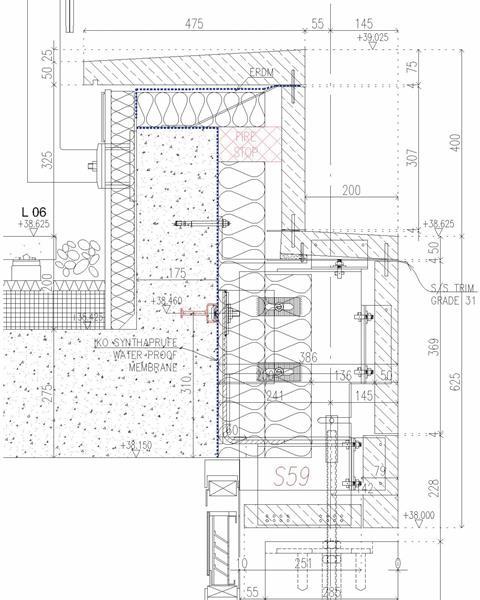
The diagram here shows the design detail where it could have been possible to extend the primary structure out a little further into the cladding projection and still maintain adequate insulation.
Another classic design detail is the “movement joint”, something hated by architects, revered by engineers and completely overlooked by the general public. Back in the days of traditional building using solid loadbearing masonry walls, there were no movement joints. But introduce the modern concrete and steel framed building with cavity walls, and movement joints at slab level become necessary. With careful design detailing these joints can be hidden, but this can become a complicated process.
Reasons for hiding or moving movement joints vary, but a particularly relevant one is when recreating a historic facade design, given that actual historic facades do not have movement joints. An example of this is a project to be built in the neoclassical style and calling for four storeys of stacked stone, no movement joints. This is a tall order for 14 metres’ height of facade, but can be done. Substantial bracketry would be designed to take the load at the bottom, with a movement joint hidden at the base. The four storeys of stone at 75mm thickness have to be designed to be effectively a single wall leaf moving in unison together, then account for the four slab edges, which move differently. This results in the design of a sliding or flexible restraint system that allows for differential movement at slab edges and avoids unwanted stresses building within the brittle facade that can cause failures. In addition window heads must be designed to act as lintels to avoid the use of local support brackets to structure. This can be done with the use of steel or concrete backed window head stones or simply by using a single spanning masonry panel if the opening is not too large.
Size counts; it is that simple. For handset stone or faience facades the size of the units that form the design affect everything, from cost to installation, to manufacture, to programme to actual viability. Design the units too small and costs quickly escalate in fixings and time on site. For handset faience facades one of the keys to economy is a rationalised design where the number of different elements that require different moulds for manufacture is kept to a minimum.
If advice is sought early in the design process, this can guide that process along the best route and prevent having to completely revisit the designs to rationalise them at tender stage. If the units are too big then the fixings and supporting systems have to be equally robust, which equates to added cost and difficulty in installation; in these cases the strength of the material is also a consideration. A recent project example is a residential building in a neoclassical style with a solid masonry wall build up. The design called for lintels 3m-long, 300mm wide and 400mm high. The chosen stone block size and the intrinsic strength of the stone did not allow for this in one piece. The lintels, which are self-loadbearing to avoid movement joints, were developed into a hybrid stone and steel lintel restrained back to primary structure.
Anything can be designed and solutions can always (nearly always) be found to make a design work. The key is in engaging with the specialist subcontract design team early in the design process, and joined-up communication with all of the team to progress the project in the most efficient way possible.
Szerelmey are specialists in the design, supply and installation of stone/faience cladding, interiors, hard landscaping and all types of restoration.


No comments yet