Constructing a six-lane road link across the River Mersey involved several challenges, not least using an asymmetrical design as a result of being on the flightpath to John Lennon airport. Andy Pearson reports on the techniques being used in the huge infrastructure project
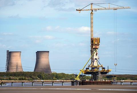
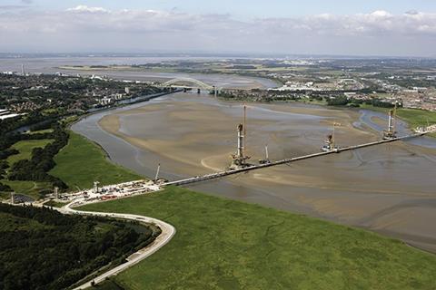
Gusting wind buffets the three concrete pylons that rise up from the broad expanse of muddy sand exposed in the River Mersey by the ebb tide. The pylons are the supports for a new six-lane cable-stayed bridge being built across the river. It will link the Cheshire towns of Runcorn in the south with Widnes to the north.
Each pylon is crowned by the red steel frame of a concrete jump-form rig chaperoned by a towering yellow crane. Today the jump-form rigs are idle; their lofty yellow companions, which would normally feed the rigs’ voracious appetite for concrete and steel reinforcement, have been immobilised by the incessant wind. “Its far too windy for the cranes to work today,” says Jim Rice, Kier’s senior operations manager.
Jump-forming is just one of the technologies that the joint venture team of Kier Infrastructure and Overseas, Samsung C&T and FCC Construcción are using to build the giant new toll bridge across this transient, watery landscape as part of the Mersey Gateway Project. As well as the cable-stayed bridge, this enormous design-build-finance-operate (DBFO) infrastructure project includes construction of a 9.2km road network, including 12 new or refurbished bridges, to assimilate the new river crossing into the North-east’s motorway network.
The giant cable-stayed bridge is the most iconic element of this huge infrastructure project and is, literally, its centrepiece. Its distinctive, asymmetrical three-pylon profile is formed by a short central pylon flanked by two, taller outer-pylons, each of different heights. Its unusual form is in response to the site’s proximity to the flight paths into, and out of, Liverpool John Lennon airport, which restricted the pylon’s height to a maximum of 125m. “Had the airport been further away, the bridge would have had a more conventional two-pylon form,” says Hugh O’Connor, general manager for Merseylink, the DBFO organisation.
Construction of the 125m-high southern bridge pylon is the most advanced; its self-propelled jump-form rig is already close to the boom of its accompanying tower crane. The 110m-high northern pylon is fast approaching its final height too, the circular plates that receive the cable stays that support the bridge deck clearly visible dotted on its vertical flanks. Construction of the 85m-high central pylon is least advanced; its jump-form rig has only recently been assembled. As well as supporting the bridge deck, this pylon is also the fixed element of the structure; expansion and contraction of the bridge deck will take place either side.
Leaps and bounds
Once the wind speed drops the central pylon’s jump-form rig will start its journey upwards in 5m leaps. Jump-form technology, as opposed to slip-form, is used to construct the concrete pylons to allow installation of the complicated reinforcement at the point where the cable stays attach to the pylons. “It is a very complex rebar arrangement at this point; we couldn’t do it as a continuous pour because of all the rebar and cable anchor boxes have to be inserted,” says Rice.
Materials including concrete and pre-assembled rebar cages are delivered to the base of each pylon by vehicle along a purpose built, 1km long, two-lane trestle bridge that spans the Mersey. The trestle links all three pylons to the concrete batching plants located on both the river’s north and south banks (see box). The trestle was also key to construction of the cofferdams that enabled the pylon bases to be constructed in the tidal river at the outset of the project (see box).
While the jump-form rigs will continue to grow the pylons skywards over the next few weeks, giant movable concrete moulds, known as form-travellers, are set to start to grow the bridge deck horizontally out from the three pylons. Currently the form-travellers’ bright blue and bright yellow frames are clamped together in pairs around the base of each pylon while the first sections of the bridge deck are cast. This month each pair of form travellers was due to be separated to enable the bridge deck to grow out from the pylons.
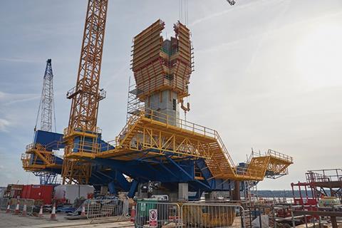
The form-travellers will move out simultaneously from each pylon, in counterbalanced pairs. They will cast the six-lane bridge deck and trapezoidal box section beneath, which provides the deck’s torsional stiffness, in 6m lengths. Initially the deck sections will be cantilevered from the pylon base, but as the length of the spans increase the deck sections will be connected to the concrete pylons by the stay cable.
Eventually the form-travellers will meet up with their counterparts from the adjacent pylon in the middle of each span. The ends of the 1,000m-long bridge deck join up with elevated concrete viaducts, currently under construction.
The movable scaffold system
The viaducts are being built on both sides of the river using a movable scaffold system (MSS). This technology is similar to that of the form-travellers being used to construct the reinforced concrete bridge deck. While the bridge deck is straight, however, the MSS enables the reinforced concrete viaduct deck to be cast as a series of sweeping, elevated curves. And unlike the form-travellers, which cast the entire width of the bridge deck, the MSS is only used to cast the central box section of the viaduct deck.
MSS technology was used to enable the central section of the road deck to be constructed on top of the viaduct’s concrete supporting piers. “The viaduct is being built above a salt marsh. If we had built it using a traditional formwork solution we’d have had to put down very substantial foundations to carry the formwork along the entire route,” says Merseylink’s O’Connor.
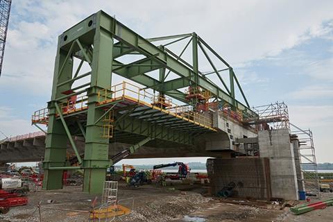
“The other deciding factor in opting to use an MSS solution is that the viaduct had to fly over the Manchester Ship Canal, and the only way we could build that section is by using a system like the MSS in any case,” he adds.
The machines are huge, even compared with the mobile form-travellers used for the bridge deck. Designed and built for this project, each is 157m long, 22m wide and weigh 1700 tonnes.
South of the river a bright red MSS is being assembled. Its two giant supporting girders have already been placed on top of landing skids attached high up on two of the viaduct’s concrete piers close to the point at which the viaduct will span the Manchester Ship Canal.
The MSS being used to construct the northern approach viaduct is identical in every aspect to its southern sister except that it is bright orange. This MSS has been in operation since January. It has already completed several of the 11 viaduct spans of the bridge’s northern approach in its advance towards the river. The MSS moves on hydraulic jacks to form the central web of the viaduct.
These machines comprise two massive steel girders each supporting half of a trough-shaped mould into which shuttering is placed to form the viaduct deck. To enable the viaduct’s deck to be cast, the girders are effectively clamped onto the concrete piers that will support the new road above the marshes so that the two halves of the mould meet. The MSS is currently locked onto two of these bridge piers. The girders form a 70m straight line between piers. The trough-shaped mould, however, incorporates hinged elements to allow the constructors to form bends and changes in camber in the viaduct deck as it sweeps around to link to the bridge. “We think this is the second largest MSS in the world, but the only one that turns corners,” says O’Connor.
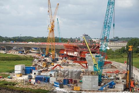
To keep the viaduct deck in equilibrium while it is being built, the MSS is positioned so that it is 15m past the first pier, meaning that it overhangs the subsequent pier by 15m. The second pier acts as a fulcrum; the downward force created by the overhanging deck section helps provide an upward force to the central deck section.
The central section of the viaduct deck is post-tensioned both longitudinally and laterally. On site, shuttering and steel reinforcement have already been placed inside the trough-like mould. A series of white plastic tubes are being threaded through the reinforcement assembly to house post-tensioning cables before the upper layer of shuttering is positioned. The tubes run along the lines of greatest tension in the bridge deck; longitudinally they follow a similar route to that of a rope suspended between the concrete piers, rising up at the piers and dropping down in centre of the span. Once the bridge deck has been cast, the post-tensioning cables will be tightened before grout is pumped into the tubes to create a monolithic structure.
The team manning the MSS works on a 22-day cycle from one concrete pour to the next. Each pour uses 1,200m3 of concrete. “The concrete is a pure OPC mix to make it rapid-hardening, because the whole operation depends on cycle times, we cannot wait 28 days for it to gain strength,” says Keir’s Rice.
Once the concrete has hardened enough, the MSS is split back into two halves to release the newly cast central section of viaduct deck from the mould. The MSS then pulls itself along 1m at a time until it has moved another 70m closer to the bridge ready to cast the next deck section.
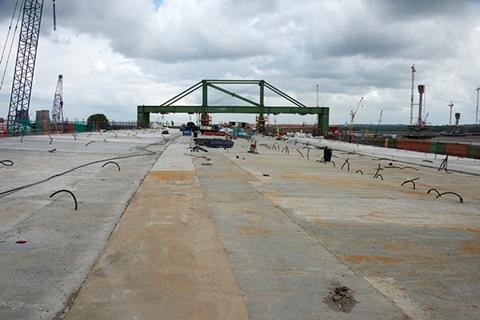
Chasing the MSS southwards is another mobile bridge construction machine, the Cantilever Wing-Traveller. It is effectively a 270 tonne, 40m-wide gantry mounted on temporary rails that have been placed on the deck section formed by the MSS. The arms of the gantry overhang the central deck on each side to suspend formwork beneath it. The formwork enables the cantilevered outer wings of the viaduct deck to be cast either side of the central trapezoidal box section to create the six-lane viaduct deck.
The wings project 6m out from the central box section and are cast in 12m lengths; 40m3 of concrete is poured simultaneously on both sides of the trapezoidal box. “It is a complex enough pour to form the trapezoidal box. It would have been a step too far to cast the wings too, so we cast them separately,” says Sean Jeffery, executive managing director of Kier.
The bridge and its accompanying road network is set to open autumn 2017. And, when it does, the joint venture team will then turn its attention to removing the trestle bridge and the temporary haul road to help minimise the contractor’s impact on this wild, windy landscape.
Project Team
Construction JV Kier; Samsung C&T ECUK; FCC Construcción S.A.
Design JV Flint & Neill; Aecom; Fhecor; Eptisa
How the trestle bridge was constructed
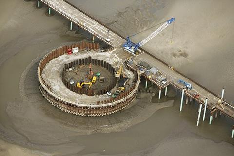
The temporary trestle constructed 8m above high water is more than 1km long to span the width of the River Mersey. Construction of the trestle began in May 2014 when a set of temporary haul routes were built by placing more than 200,000 tonnes of stone on geotextile membranes. The haul roads cross the salt marshes on both sides of the estuary to enable the construction teams to reach the river.
The trestle bridge was assembled simultaneously from both banks of the river. First a pair of piles were sunk into the river bed 12m apart. A header beam was then placed on the piles and a pre-assembled 12m-long section of steel trestle deck lowered onto the piles. Then concrete planks were placed on the deck to form the two-lane carriageway. By working from the newly constructed section of carriageway the next pair of piles could be sunk, and so on until the two halves met in the middle of the river.
How the pylon bases were constructed
The foundations for the three bridge pylons had to be constructed in the riverbed, below water level.
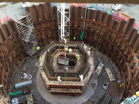
To create a water-free environment, cofferdams are used to form temporary watertight enclosures using sheetpiles.
Two rings of sheet piles are used, a 40m diameter outer circle and an inner circle of 20m. The annulus between the inner and outer pile rings was then filled with stone to create a working platform to allow excavation of the inner circle, down to bedrock.
Once down to the bedrock, a concrete floor is created to support the 190 tonnes of reinforcement for the pad foundation and 1,400m3 of concrete poured over a period of 26 hours. With the foundations in place, the pylon shaft could then be constructed. A jump-form rig was used to construct the tapering pylon base up to the “hammer head” on which the deck sits.








No comments yet