


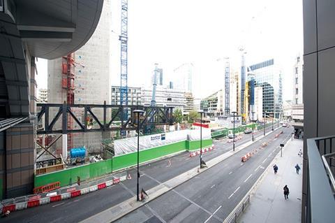
The construction team working on London Wall Place have extended the usable space of one of the buildings by cantilevering 15 floors of offices out over the pavement by a breathtaking 11 metres
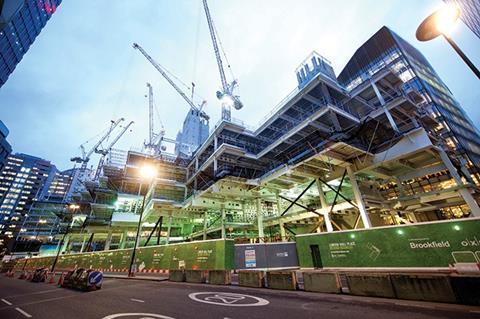
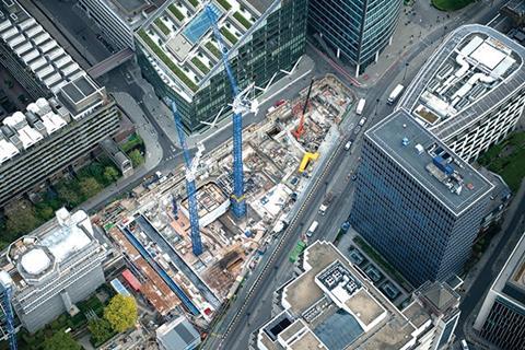
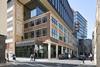
Mega is a word that crops up frequently on Phil Clarke’s tour of London Wall Place. Clarke is project director for Brookfield Multiplex Construction, the design and build contractor responsible for the 46,000m2 scheme to deliver two landmark office buildings and a large landscaped area of public realm all within a champagne cork’s popping distance of the residents of London’s Barbican Centre.
Striding purposefully round the site, his name writ large on his white hard hat, he points out the “mega-column” which supports the “mega-truss” before describing the challenges of installing the 70 tonne “mega-beam”. He could easily add mega structural engineering feat and mega construction challenge to his description of the project.
This is a challenging City of London site. “All manner of utilities, services and infrastructure” have, in Clarke’s words, placed constraints on the foundations for the scheme’s two new office buildings. Yet, in spite of these limitations, Make Architects’ design for joint venture developer Brookfield Property Partners and Oxford Properties manages to wrest every last square metre of office space from the site.
That Make has succeeded in achieving this is due in no small part to some remarkable structural engineering by WSP Parsons Brinckerhoff. This has enabled the buildings to offer up space well beyond their basement boundary by incorporating huge cantilevers and giant transfer structures.
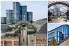
The 16-storey Two London Wall Place is the closer of the two buildings to Clarke’s site office. Construction of its large slip-form concrete core is complete and erection of its steel structure has now reached the roof. At first glance this would appear to be a fairly conventional office tower – that is, until you notice that the tower’s south-east corner has no supporting columns at pavement level so that, when it’s built, 15 floors of offices will cantilever out over the pavement by an astounding 11m.
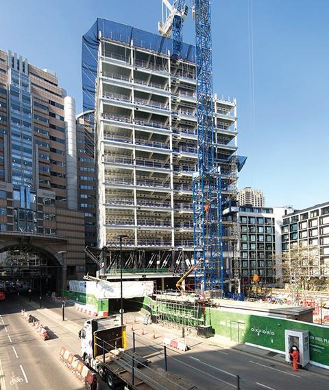
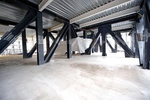
It is this giant cantilever that Clarke’s aforesaid mega-truss and mega column support. In the building’s unclad-state, the vertical, horizontal and angled steel members of the braced, cellular mega-truss are clearly visible between the building’s first and second floor slabs. Clarke’s “mega” prefix could not be more apposite: the truss is so large that its black bolted steels actually occupies the entire storey height.
Sections of the truss line the perimeter of the two floorplates, while other sections tie the truss back to the building’s core. This truss will enable the upper floors to cantilever out by 35m on the building’s southern elevation and by 16m on its eastern elevation. The closest supporting column is 11m from the tip of the cantilever. Unsurprisingly, given the loading on it, this is Clarke’s “mega-column”, which he explains is carrying a load of “50 meganewtons” down to the building’s piled foundations. This is equivalent to the load of about 50 floors of a conventional office building.
In contrast to the rest of the steel structure, which has a white, intumescent paint finish, the steelwork forming this huge truss has been painted dark grey on the basis that the dark colour will reduce its impact when viewed from outside behind the building’s glazed facade when the floor is eventually let to a restaurant tenant.
Structural engineer WSP Parsons Brinckerhoff considered various supporting options for this cantilever including: construction of a vierendeel facade, the use of raking columns, and even suspending the entire corner of the building from roof-level trusses. The giant truss was, however, considered the most efficient solution. “It also had the advantage that it allowed the building to be constructed in sequence,” explains the project’s structural engineer Stephen Jackson, a director of WSP who has joined Clarke on his whistle-stop site tour.
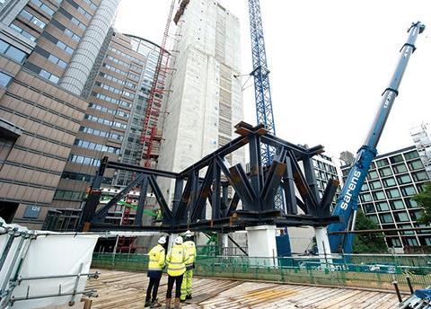
Erection of the giant truss presented Brookfield Multiplex with a considerable challenge, mainly because the giant steel sections from which it is assembled are too heavy for the site’s tower cranes. To make the steel sections easier to transport steelwork subcontractor William Hare fabricated the larger trusses in quarter sections; halving them in length and width. Even in quarters the 20 tonne sections were still too heavy for the tower cranes so Brookfield Multiplex devised a solution using a large 500 tonne mobile crane to hoist the sections into position. “The difference between this development and others that have gone up in the City is that we had to use mobile cranes because the weight of the pieces of steel is way beyond what a tower crane can lift,” explains Clarke.
Sections of the steel truss are bolted together. A welded solution was considered but the site’s proximity to the residential enclave of the Barbican means it has to operate under a strict time regime (8am to 6pm Monday to Friday and 9am to 2pm on Saturdays) and there were concerns that the size of these huge steel sections would require 24-hour working. The bolted solution also had the advantage that it allowed the truss to be trial-assembled prior to delivery.
William Hare has fabricated the truss so that in its unloaded condition, the tip of the cantilever is artificially raised. On site the addition of steel shims on top of the mega-column and temporary bracing helped maintain the pre-set while the truss was being bolted together.
Now, under the steadily increasing weight of the steel frame combined with weight of the poured concrete floor slabs, the truss is starting to flex. By the time the cladding has been added to all 15 floors supported by the truss, the truss will have levelled out. In fact, when the building is fully occupied and the floors fully loaded, the truss will actually deflect downwards very slightly. “The tip of the cantilever is pre-set at +15mm; it is expected to drop to -20mm when it is fully loaded,” explains WSP’s Jackson.
In addition to its weight, the incorporation of a truss designed to flex as it is loaded means that its construction has to be planned to accommodate the movement. “The challenge programme-wise has been to get the cantilever to the right position with temporary works and pre-setting, then to get enough of the structure built above so that it creates sufficient mass to level-off the pre-set to something close to its final position so that we are in a position to start installing the cladding,” explains Clarke. “We’ve concreted the floor plates to level 8 and our graph shows that the truss deflection is in line with expectations.”
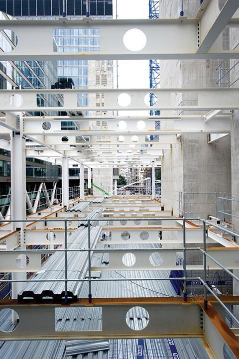
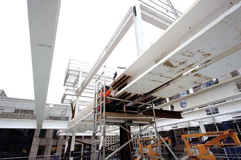
Work to concrete the floor plates has now reached level 6 on the second of the scheme’s two office buildings – the 28,000m2 One London Wall Place. This 12-storey building will be asset manager Schroders’ new London HQ. While not as tall as its neighbour, the building’s southern elevation nevertheless incorporates a series of seven giant cantilevered beams. These vary in projection and are arranged so that in plan the elevation fronting London Wall forms a saw-tooth arrangement overhanging London Wall. “Although the superstructure extends horizontally outside the basement perimeter we could not put columns outside of the basement because of all the services running around its perimeter,” explains WSP’s Stephen Jackson. “This solution also helps to minimise the columns landing at ground level disrupting the public realm experience.”
These cantilevers, some of which project for up to 9m, pick up the load from columns above and transfer them to pile foundations inside the basement. “On the southern elevation, where all of the big cantilevers are concentrated, there are some really high column loads to drag the loads from higher up the building back to within the basement,” Jackson explains.
On One London Wall Place all of the cantilevered beams are located at second floor level. The magnitude of the loads means that the beams are up to 2m deep fabricated from heavy steel plate. “The heaviest is the 72 tonne mega-beam, which is 50 times the weight you’d normally expect for a beam on a similar scheme,” says Clarke. The weight of these huge beams meant that, as with the mega-truss, a mobile crane had to be used to lift them into place.
The building’s northern elevation also features heavy beams. In contrast to the vertical southern elevation, the building’s northern elevation steps down towards the Barbican in a series of grassy terraces. Each terrace is supported on columns. However, rather than clutter the floorplates with rows of terrace-supporting columns, to maximise the use of office space, the columns are truncated so that they sit on transfer beams located at high level on the floor below. The number of terraces means that there are transfer beams at almost every floor. The beams transfer the loads to columns forming the building’s main structural grid. “Every time you introduce a terrace you end up with a beam that picks up the load from the column above,” says Clarke.
In order to limit the depth of these beams, while ensuring they can cope with the high loads imposed on them, some of the transfer beams are actually formed from two parallel smaller-section beams. However, even with this arrangement, the limited carrying capacity of the tower cranes meant that the smaller section beams had to be fabricated in two parts, which are then bolted together once the beam in position. “Where each transfer beam becomes a double beam it requires a total of 10 crane lifts to install,” Clarke explains.
It is not just the facade that incorporates cantilevers; on this building even one of its cores features a cantilever. One London Wall Place has a main central core and one satellite core, which house lift shafts, escape stairs and service risers. It is at second floor level that one of the satellite cores has been designed to cantilever out over the footpath and one of the scheme’s elevated walkways. The engineers have been able to do this by transferring the stairs from within the core to inside the building.
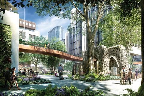
The scheme also includes six new footbridges some of which are, of course, cantilevered. The site was originally occupied by St Alphage House, a 22-storey 1960s office building and an accompanying high-level pedestrian podium, which linked the elevated walkways of the Barbican to Guildhall. With the office and podium demolished to make way for this project, the high level pedestrian routes are to be reinstated using new weathered steel bridges.
To overcome any structural capacity issues with the neighbouring buildings, all of the bridges have been designed to be largely supported from the new scheme. The bridges take two forms, tubular box girder sections where suspended by the new buildings and U-shaped steel box section structures incorporating rigid parapets to enhance their stiffness when cantilevering from the new development. Two of the cantilevered bridges also incorporate a pylon and cable stays.
The longest and most spectacular of the bridges spans the 35m gap between the two new buildings. It is made up of two balanced sections that give the appearance of cantilevers, which meet at the point where the bridge gently curves around the historic remains of the 14th-century St Alphage Church Tower. This bridge has yet to be installed, which is a shame because it does not feature in Clarke’s site tour, but when it does it will no doubt be the Mega-bridge.
Project Team
Developer Brookfield Property Partners and Oxford Properties
Architect Make
Structural engineer WSP Parsons Brinckerhoff
Services engineer HurleyPalmerFlatt
Cost management Gardiner & Theobald
Space planning KKS Strategy
D&B contractor Brookfield Multiplex


No comments yet