


Our blogger overcomes the major challenge of making the junctions between the floor beams and walls airtight: here's how...
I’m just back from an enjoyable bank holiday weekend in Machynlleth, mid-Wales with my motorcycling mates. It was a bit of busman’s holiday as I ended up having several meetings with some of the building experts at the Centre for Alternative Technology (CAT) – who were all being very supportive and enthusiastic about Passivhaus developments.
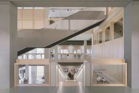
I also spent an evening in the pub with John Williamson of JPW Construction the designer of Canolfan Hyddgen – the first and (currently) only certified Passivhaus building in the UK, also based in Machynnlleth.
The building is actually an educational IT centre built for Powys Council to Passivhaus standards. Much larger than our project and built in a very different way, but still using all the same principles.
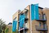
Built with a timber-framed construction, Canolfan Hyddgen uses 300mm insulation, triple-glazed windows and has an airtightness of under 0.6 air changes per hour at 50Pa. The ducting for the MVHR system throughout the building was all very visible in an industrial way – very Pompidou Centre.
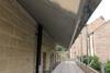
With lots of south facing windows, IT equipment and occupants there is the potential for overheating in the building. To address this they have used a large eaves overhang to the roof for shading to first floor windows and a galvanised steel pergola/brise-soleil system for shading ground floor windows.
I found the building very peaceful and quiet – helped by the triple glazing and airtightness – with a pleasant ambience and even temperature (in this case relatively cool as it was warm outside).
The air quality was good because it was controlled - airtightness doesn’t mean suffocation it just means you control the ventilation. I found it really a comfortable pleasant building to be in, as I’ve found with the other Passivhaus buildings I visited in Germany last year, and I’m looking forward to the Denby Dale Passivhaus performing as well when completed
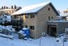
On site with Denby Dale
I’m really pleased with how the team are doing on site. All the work put into careful detailing for the PHPP over the last two years has paid off in making the build go so smoothly now.
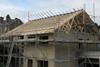
We’re now at roof level with the blockwork – the steel frame for the solar space is now up and plywood boxes for the windows all in place. The garage is now up with the flat roof ready for the patio later (to be completed in a later phase). The first floor I-beam joists are all in place which will be discussed in more detail below.
First floor junctions
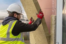
In a Passivhaus it is vitally important to ensure airtightness around junctions between the first floor beams and walls. Traditionally a normal masonry cavity wall construction would build the timber first floor joists directly into the inner leaf. Although this ensures good stability it is disastrous in terms of airtightness because of the differential shrinkage that occurs when the timber dries out against the masonry. This occurs around every joist end which, if you add it up throughout the building, amounts to a tremendous draught, probably the equivalent of someone leaving a window or door open.
There are many different approaches which can help reduce this problem. In the Longwood House, which we built in the early 1990s before we knew about Passivhaus design (and even before the Passivhaus concept had properly been developed!), we came up with a simple solution of placing formwork noggins between the joists about 25mm away from the blockwork to allow us to squirt foam in the cavity formed to improve the airtightness between joist ends and cavity wall. We also brought the wet plaster right down to floor to further help. Revolutionary techniques like this helped us achieve an airtightness level of three air changes per hour.
For the Denby Dale Passivhaus we need to get airtightness levels down to 0.6 air changes (that’s five times better) so we needed to come up with an even better solution. Firstly, though, a word about how we chose timber I-Beams from all the flooring options open to us.
Using suspended insitu cast concrete would have been very good from an airtightness and energy efficiency point of view as the slab is carried into the wall in one continuous airtight form in a similar way to our detail for ground floor. The concrete floor would expand and contract in the same way as the blockwork, as it is made of the same material. Another advantage would be that it would provide thermal mass – the ‘cave effect’ that we’ve talked about previously.
The disadvantages of this system is that the UK construction industry is not really set up to do this, the formwork would have been a relatively expensive procedure and also that it offered no space for services, in particular the MVHR system.
We could also have gone for the pre-cast beam and block system which has the advantage of providing thermal mass without the need for formwork. However, because it is in component form there would still be a chance of air movement through gaps etc.
It would have been possible to overcome this by wrapping a robust breathable airtightness membrane such as Pro Clima Solitex Plus around the ends of the blocks as they go into the cavity, and then sealing the Solitex into the wet plaster. However, again we were concerned as to where to put the services and MVHR system, so we rejected this method.
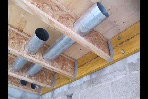
In the end we opted for a 302mm deep timber I-Beam system based on buildability, price and speed, but mainly because of its ability to take the MVHR ducting through the beams (up to 150mm diameter). Some Passivhaus buildings have the MVHR ducting boxed below the ceiling level or at skirting level, but we decided that concealing it in the first floor I-beam structure would be neater.
To avoid the common airtightness problems associated with cavity wall we have not taken the I-Beam floor joists through the blockwork. Instead we’ve developed a detail to fix them in place without seriously puncturing the blockwork.
Firstly we parged the blockwork wall using a sand and cement mix to make the blockwork more airtight (wet plaster will be used on the rest of the walls, of course, but this can only be done once the floor is in place).
We then fixed a 45mm/302mm laminated timber wall plate to the already-parged blockwork. We have used stainless steel threaded bar with washers and nuts, which were carefully taken approximately 75mm into the 100mm blockwork.
We then applied epoxy resin into the holes to act as a further airtightess barrier as well as an anchor making very sure that there was enough resin to squeeze out and correct any damage to the parge coat.
The I-beam joists were attached with normal ‘timber to timber’ steel hangers. As a further ‘belt and braces’ airtightness measure we’ve masticked the top and bottom of the wall plate to the blockwork wall with Pro Clima Orcon F. At a later stage, glued tongue and groove chipboard flooring will be screwed to the I -Beam joists to give further stability. Hopefully the diagram below will illustrate this detailing:

1. Sand and cement parging
2. Two coat plaster
3. Versalam engineered timber wall plate
4. 302mm plywood I beam floor joist
5. Service voids
6. Resin achored stainless steel threaded bar
7. Metal joist hanger
8. 12.5mm plasterboard and skim
9. 20mm T&G chipboard flooring
Postscript
Bill Butcher is director at Green Building Store


2 Readers' comments