


How the team tackled difficult conditions on the site of the 2014 Commonwealth Games centrepiece
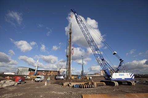
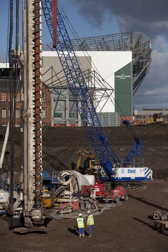
The National Indoor Sports Arena and the Sir Chris Hoy Velodrome will be the spectacular centrepiece of the 2014 Commonwealth Games, hosted by the City of Glasgow in four years time.
Designed by sports venue specialist Sports Concepts with 3DReid as delivery architect and Halcrow Yolles as civil and structural engineer, the £116m arena will comprise three linked buildings: a 5,000-seat indoor arena, complete with a banked running track, a 4,000 capacity velodrome and a community sports facilities.
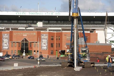
This stunning new venue is under construction on one of the most difficult sites in Glasgow. A ground survey of the 10.5ha former industrial and residential site on the banks of the River Clyde in the east of the city showed that the brownfield site’s soft ground was a mixture of materials including: sand, silt, river gravels, clay and fill-material left over from the site’s industrial past.
It was obvious that if a landmark sports venue was going to be built on this particular site, the ground engineering team would need to engineer a solution ensure the assortment of ground conditions were capable of supporting the various loads imposed on it by the structure – with such a variety of ground conditions the project was going to need some very impressive ground engineering.
In response to the difficult ground conditions, Halcrow Yolles proposed five different piling and ground improvement techniques to ensure the site could support the loads imposed on it by the new arena.
Following a competitive tender, Balfour Beatty Ground Engineering (BBGE) was awarded the £1.2m piling contract by main contractor Sir Robert McAlpine on the basis that the company had the capability and capacity to undertake all of the various piling and ground improvement techniques in-house. For McAlpine, this ensured the ground engineering package could be let as one contract.
This had the benefits that the main contractor only had one point of contact for the entire piling contract and that responsibility for coordinating the different techniques could be handed to the contractor. “Balfour Beatty Ground Engineering won the tender because it has the capability to undertake all the different piling and ground improvement techniques needed for the site,” says Lindsay Archibald, contract manager for BBGE’s piling division.
The firm’s early involvement in the scheme allowed the contractor to use its vast experience to propose the most cost effective ground engineering solutions for the site (see box: The five different ground engineering techniques used by Balfour Beatty Ground Engineering on the construction of the NISA, below).
For example, originally a mixture of driven pre-cast and rotary piles had been specified for the velodrome site’s higher ground areas. However, by adapting the design of the pile caps for the pre-cast concrete piles to enable them to support a heavier load, BBGE was able to eliminate the need for the installation of more complex and expensive rotary piling at this level.
BBGE started piling in January 2010. When the contractor arrived on site the ground had already been remediated and shelves had been cut into the sloping site to level it ready to accommodate the new structure.
Programming the different techniques for the site was challenging because some of the systems were being used on several areas of the site at the same time. It was a task made all the more challenging by the severe winter weather, which resulted in some of the works having to be rescheduled because the top layers of the ground froze in the extreme low temperatures.
It was a challenging contract, but after 10 weeks Balfour Beatty Ground Engineering completed the contract, including testing the piles, on time and on budget. Their achievement enabled the contractor to hand over the construction baton to the ground works contractor so that it could begin the next leg of the arena’s construction in the race to complete the stadium ready for the games.
The five techniques
The five different ground engineering techniques used by Balfour Beatty Ground Engineering on the construction of the NISA:
Dynamic compaction
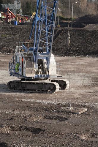
The ground where the main arena was to be sited was a loose granular mix of sand and gravel. Dynamic compaction was used to stabilise the area. The technique works by repeatedly dropping a heavy weight onto the ground to compact the soil, inducing settlement at depths of up to 8m and ensuring any voids in the ground are closed.
To ensure the ground is compacted evenly, BBGE used a 5m grid system to determine precisely where to drop the 8 tonne weight. The weight itself is actually a 2m square, 150mm thick section of steel plate, dropped from a crawler crane. For the first pass across the site, the weight was dropped about 10 to 12 times from a height of 15m at each grid intersection point. This high-energy treatment is intended to compact the deep soil layers. The crane traversed the site a second time; this time, however, the weight was dropped in the middle of each grid square to ensure the ground was thoroughly and evenly compacted.
Depending on the ground conditions, the resulting impact can form a crater up to 1m deep, lowering the site level. To return the ground level to the appropriate level, additional material is added to the site following each pass. For the third and final pass across the site, the weight is dropped from a much lower height across the entire treated area to “tamp down” the surface soils disturbed by the previous two passes, explains Archibald. The bearing capacity of the treated ground was improved sufficiently to comply with the stringent settlement criteria specified for the arena’s floor slab.
Advantages:
Cost effective over a large area because excavation is not required. No spoil is generated by this technique.
Disadvantages:
Because of the likelihood of flying debris as a result of the impact and other risks associated dropping a large weight onto the ground from a crane the system is only suitable for large open sites and is not suitable for use within 30m to 50m of an existing structure or within 30-50m of any other site activity. Not suitable for soils with predominantly clay content.
Vibro stone columns
Vibro stone columns (VSCs) were installed beneath the velodrome to support the foundations for retaining walls, service tunnels and velodrome track structures because the amount of clay present in the ground prohibited the use of dynamic compaction to as a ground stabilisation method
VSCs are one of the most commonly specified ground improvement methods because they are relatively cheap and easy to install and can be tailored to suit a wide variety of ground conditions and bearing capacities. At the velodrome, over 1200 vibro stone columns, to provide a bearing capacity of 150kN/m2, have been installed.
The vibro stone columns were constructed by vibrating a 400 mm diameter poker – the vibroflot- into the ground under its own weight creating a vertical shaft. As the vibroflot penetrates the ground, pressurised air is used to aid penetration and stabilise the bores. A custom built Casagrande B170VF rig was used to install the columns at depths of up to 10m. Once the design depth has been reached the borehole is progressively filled with small stones of between 20-40mm diameters, which are compacted using the vibroflot so that, eventually, they form a column of stone.
At the velodrome there were concerns that the walls of the bores would collapse because the ground was so weak if the vibroflot had been removed to pour in the stone fill. Balfour Beatty Ground Engineering’s solution was to use the curious sounding “dry bottom feed method” to construct the stone columns. This method works by introducing a charge of stone directly to the base of the shaft, through a pipe attached to the side of the vibroflot. The vibroflot is then used to pack the stones together. This process is repeated with a new charge of stone until a column of compacted stone extends the full height of the shaft. In addition to compressing the stones in the shaft, the vibration process helps drive the stones into the soil surrounding the shaft, improving the relative density of the ground and creating a stone column about 600 mm in diameter.
Some of the holes for the vibro stone columns had to be pre-drilled. This was because an old railway embankment had originally crossed the site. Over time the weight of the embankment and the vibration of the trains trundling along it, had compacted the ground’s upper layers making it too dense for the vibroflot to penetrate un-aided. In this area the top 3-4m of the VSC shafts were pre-bored using a Soiltek S60 rig. Once the dense ground had been penetrated, Balfour Beatty Ground Engineering used the vibroflot system to finish the shaft’s construction in the softer ground below.
Advantages:
VSCs are relatively cheap and easy to install and suitable for a wide variety of ground conditions. It is a displacement technique with no spoil arisings, meaning that VSCs can be a highly sustainable solution for ground improvement problems.
Disadvantages:
No lateral or tensile strength. When stone columns are used for foundations (rather than for ground stabilisation) more columns are used than piles.
Continuous flight auger
The increased loads of up to 4500 kN beneath the remainder of the velodrome structure and the majority of arena’s structure demanded a heavy duty approach to ground engineering, which was where the cast in-situ reinforced concrete piles were used. Two different types of pile were used for the indoor arena – continuous flight auger and large diameter piles.
As the more economical solution Continuous Flight Auger (CFA) piles were used in preference to large diameter rotary bored piles (see below), wherever possible. CFA piles are constructed by rotating a single auger. The auger supports the walls of the shaft as it penetrates the ground. Once the auger reaches the design depth it is removed. At the same time as the auger is being withdrawn from the shaft, concrete is pumped through the centre of the auger to the foot of the pile to form a continuous column of concrete up to ground level. With the auger removed, a steel reinforcing cage up to 17m in length is then lowered into the concrete and vibrated into position to add lateral strength to the pile.
A Soilmec SF120 rig was used to drill the project’s 207 piles. The piles are positioned beneath the structure and the rig used two different auger diameters – 600mm and 750mm depending on the magnitude of the compressive and lateral forces exerted on the pile. Because the soils were so poor, in some areas of the site the piles had to reach down 31.5m to find suitable ground.
Advantages:
The piles can support relatively high loads and they are cheaper and easier to install than large diameter rotary bored piles.
Disadvantages:
Cannot be installed as deep as rotary bored piles because the depth of the piles is limited by the length of the auger
Large diameter rotary bored piles
Large diameter rotary bored piles (LDP) are constructed using an auger. However, the auger for this type of pile is much shorter than that used for CFA piles. The auger penetrates the ground until it is fully embedded then it is pulled to the surface and spun at high revolution to remove the spoil. The cycle continues until the required depth is reached.
To keep the bore open, a temporary hollow sleeve was fitted around the top of the shaft to support its walls in the soft soils near to the surface. As the bore becomes deeper, Balfour Beatty Ground Engineering pump a vinyl polymer slurry into the bore to support the shaft’s walls and to stop them collapsing before the concrete is placed. The polymer support fluid effectively wraps the pile bore in a cling film like material. The polymer has the additional advantage that much less equipment is needed on site to produce the slurry over the more traditional bentonite method.
Once the pile is at the design depth, a steel reinforcement cage is inserted. Concrete is then poured to the base of the pile through a tremie pipe. It is important that the end of the tremie pipe is kept below the surface of the concrete until the pouring is complete to displace the polymer and ensure pile continuity. A plug within the tremie separates the concrete from the polymer to ensure the concrete does not become segregated. Once the concrete has filled the pile the hollow support sleeve is removed.
The advantage of this system of piling as opposed to CFA piles is that various different core barrel attachments, some with hardened teeth, can be used to penetrate the ground and drive through buried obstructions. A Casagrande B125 rig was used to construct the piles, which extend to depths beyond 32m. The finished piles are cut back to the required length onto which a pile cap is cast; the structure is then built up from this point. The piles have been designed for loads up to 4500kN/m2.
Advantages:
Can be driven deeper than CFA piles and can penetrate rocks and other underground obstructions, and can be very wide diameter.
Disadvantages:
More expensive to install than CFA
Driven precast concrete piles
These square, precast concrete piles are manufactured off-site in lengths of up to 14m in Balfour Beatty Ground Engineering’s own production facilities. The piles are driven up to 27m into the ground, using a 5 tonne hydraulic hammer mounted on a Junntan PM20 rig, until the top of the pile protrudes about 500mm from the ground. Driving the piles compresses the surrounding soil, causing greater friction on the sides of the pile and increasing their load bearing capacity. Two different pile widths were used at the NISA: 235mm wide piles for loads up to 500kN/m2, and 275mm wide piles for loads up to 700kN/m2.
For those applications where the design depth of the piles was greater than 14m, two piles were joined together using a simple interlocking pin joint. The location of the joint is critical to the performance of the pile because it will only work under compressive forces. Balfour Beatty Ground Engineering ensured the joint was always at the pile depth where it had been calculated that there were no shear or tension forces.
Because they are relatively quick and easy to install, pre-cast piles were used to support the structure in areas where the loads were light enough not to require a CFA solution.
Advantages:
Quick and easy to install and produce no spoil, have better load bearing capacity than ground conditioned by dynamic compaction
Disadvantages:
The installation process can produce significant vibration in certain ground conditions.


No comments yet