


Mott MacDonald has set itself a tough 2013 deadline for using BIM on all its projects, so it simulated a sports venue project to test out its skills
Mott MacDonald has set itself a target for using building information modelling (BIM) on every single project it works on - and the deadline is not very far away. “We want BIM to be business as usual for all of our projects by 2013,” says Richard Shennan, a director at Mott MacDonald and the company’s BIM champion.
What this means in practice is that traditional, two-dimensional drawings will be replaced by three-dimensional BIM models - each one comprising smaller 3D objects that are packed with digital information about design elements, such as their geometry or materials. The BIM model can then be shared, exported and added to by the whole design team.
The word “revolution” is never far away whenever BIM is mentioned, and it is clear that, for targets such as Mott MacDonald’s to be hit, businesses are going to have to transform the way they manage projects. Protocols need to be established, disciplines co-ordinated and potential problems flagged up. With this in mind, Mott MacDonald set itself a little sporting challenge …
Rules of the game
Last year the practice’s London office set itself the task of using BIM to design a 6,500-seat sports arena capable of hosting international, national and community gymnastics events.
This was a particularly demanding project for Mott MacDonald’s mechanical, electrical and public health (MEP) engineers to cut their BIM teeth on because of the large amount of building services that had to be co-ordinated with the architecture and structure in order to maintain a comfortable environment throughout the year.
Mott MacDonald established protocols for collaborative working at the project’s outset to enable the architectural, structural engineering and MEP teams to work together in a BIM environment. Design commenced in mid-2011 using Revit 2011 software. “It was important to define the version of Autodesk’s Revit software used because Revit is not backwards-compatible,” says Richard Clibborn, principal electrical engineer on the project. In other words, if one part of the team found itself using a more up-to-date version of the software than everybody else, the rest of the team would be unable to share its files.
Clibborn says the project team opted to use Revit 2011, which was “in common use by all design team members”, rather than the later version, Revit 2012, which had just been released.
One of the firm’s structural engineers, who was experienced at working in a BIM environment, was given the task of model manager. “Somebody has to call the shots on protocol decisions,” Shennan explains. In addition to a model manager, each discipline team also nominated “a Revit champion” to be the key contact with responsibility for the BIM model.
Rather than using a single, live BIM model for this project, the team used what Shennan refers to as a “federated” BIM model. “We’re not using a live model because it updates all of the time, so it creates a moving target for the designers,” he says. “The federated approach uses a series of models that interrelate following the collaboration principles set out in BS1192, which defines collaborative work flows.”
With the federated model, each discipline works on their frozen version of the BIM model. This was uploaded to the project site every Friday evening. Every Monday morning the team downloaded the latest drawings from the other disciplines and ran a co-ordination check. Any clashes were resolved through discussion with the BIM champion for
each discipline. “The idea is that you have people designing in an environment where things are not moving around; the design is then brought into the shared BIM model through software such as Navisworks,” explains Shennan.
A multitude of models
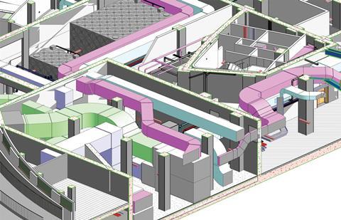
The idea of each discipline working on a frozen BIM model was taken one stage further by the MEP team. At one stage in the design, the team was running five separate BIM models including ones for lighting design, pipework, ductwork and public health. These individual models had to be combined and co-ordinated to produce the single MEP model that could be shared with the other disciplines.
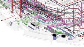
The reason for the MEP team’s multitude of models was that it was concerned that combined models would become too large and unwieldy to manipulate, share easily and export into analysis software. In the event, this turned out not to be the case and a single building services model will be used in the future. “We’ve come to the conclusion that it would have been better to have used a single MEP model because once you start adding electrical load information to items of mechanical plant the mechanical model needs to link to the electrical model in any case,” says Clibborn.
The arena’s lighting design was a critical part of the scheme. “We did a lot of work enabling 3D data for the roof structure and lighting gantries to be exported from the BIM model into lighting design software AGi32, to enable the lighting design to be developed,” Clibborn says. Once the lighting scheme had been finalised, luminaire locations and lamp aiming lines were then imported back into the main BIM model. It is a process Clibborn admits would have been much easier if the team had used the later version of Revit because AGi32 has subsequently released a Revit 2012 plug-in. This would have allowed the lighting analysis to be carried out in the BIM environment.
We’re not using a live model because it updates all of the time, so it creates a moving target for the designers
Richard Shennan, Mott MacDonald
The MEP team had to spend time developing a library of generic three-dimensional blocks of space to represent each item of plant. This was necessary because BIM models are made up of objects rather than lines on a sheet of paper. Using generic components enables space planning and service distribution routes to be established early in the design before equipment loads have been finalised and plant selected.
“I’m an electrical engineer so the generic components we’ve created include low-voltage switchboards, distribution boards and transformers to enable us to allocate space for installation and maintenance in the model,” explains Clibborn. As the scheme develops and loads are defined the generic sizes of the electrical equipment are also refined.
Three-dimensional ducts and generic components were also used to model the arena’s ventilation system. This has been designed to ensure that a comfortable environment could be maintained for competitors and audience alike in an extreme version of the UK climate where outside temperatures rise to 38°C in summer and fall to -5°C in winter.
Another ball in the air …
A major challenge with the arena’s ventilation was the need to keep the air velocities low enough to enable the arena to be used by gymnasts performing floor routines that involve tossing balls and twirling ribbons in the air. The MEP team’s solution to this conundrum has been to exploit the bowl formed around the performance space by the twin tiers of seating.
In summer, before an event takes place, the arena bowl will be filled with cool air through grills located beneath the spectators’ seats. With the event under way, the cool air supplied beneath the seats will keep the spectators comfortable and at the same time counteract the additional heat generated by the audience. Extract grilles above the stands will whisk away any warm air. In winter, warm air supplied beneath the seats will be used to heat the space.
To ensure this ventilation solution worked in both summer and winter, spatial information from the co-ordinated BIM model was exported into a Computational Fluid Dynamic (CFD) modelling package. The exercise served to highlight some important lessons regarding the protocols for creating walls in a BIM environment because when the MEP team initially tried to use the BIM output in their CFD model they found that the architectural team had incorrectly modelled the junction between the ceiling and walls so that air could escape through a gap at the top of the wall. Initially this made it impossible to run the CFD package. However, with the problem solved, modelling proved the design would maintain conditions at 20°C throughout the year.
For Robert Hunter, project manager and senior mechanical engineer on the project, the BIM exercise was worthwhile. “With an arena, it is quite highly serviced and all the services are generally quite big; this model gives us belief that the MEP scheme does co-ordinate and we know that would fit on site,” he says. “I think we’ve done really well for our first project - we exceeded our expectations of what we could achieve - although with hindsight maybe this scheme was a bit too big for this office to try out its first major Revit and BIM project,” he confides.


No comments yet