- Home
- News

All the latest updates on building safety reformRegulations latest
- Focus
- Comment
 The how and why of collaborative contracting
 Crisis management to national renewal – what does the built environment need from Andy Burnham’s first 100 days?
 What will the construction products reform white paper mean for you?
 Now Reform UK are serious contenders, should the built environment despair or rejoice?
- Events
- CPD
- Building the Future
- Jobs
- Data
- Subscribe
- Building Boardroom
Close menu
- Home
- News
- Focus
- Comment
- Events
- CPD
- Building the Future
- Jobs
- Data
- Subscribe
- Building Boardroom


Passivhaus diaries, part 15: mechanical ventilation and ducting system
By Bill Butcher and Bill Butcher Bill Butcher2009-11-30T14:31:00
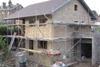
It's time to put in the MVHR unit at the Denby Dale house
Already registered? Login here
To continue enjoying Building.co.uk, sign up for free guest access
Existing subscriber? LOGIN
Stay at the forefront of thought leadership with news and analysis from award-winning journalists. Enjoy company features, CEO interviews, architectural reviews, technical project know-how and the latest innovations.
- Limited access to building.co.uk
- Breaking industry news as it happens
- Breaking, daily and weekly e-newsletters
Get your free guest access SIGN UP TODAY

Subscribe now for unlimited access
Subscribe to Building today and you will benefit from:
- Unlimited access to all stories including expert analysis and comment from industry leaders
- Our league tables, cost models and economics data
- Our online archive of over 10,000 articles
- Building magazine digital editions
- Building magazine print editions
- Printed/digital supplements
Subscribe now for unlimited access.
View our subscription options and join our community